
|
|
Forum Index : Microcontroller and PC projects : gp28 as adc
| Author | Message | ||||
| stanleyella Guru Joined: 25/06/2022 Location: United KingdomPosts: 2807 |
I built a usb hdmi board and tried adc on gp28 setpin gp28,ain 'SETPIN (34), AIn adc open 10000,3 'samples per second gives run [3] ADC open 10000,3 'samples per second Error : Pin GP26 is not off or an ADC input > option list PicoMiteHDMI MMBasic USB Version 6.00.00RC15 OPTION SERIAL CONSOLE COM2,GP8,GP9 OPTION FLASH SIZE 4194304 OPTION COLOURCODE ON OPTION KEYBOARD UK, 0, 0, 600, 150 OPTION CPUSPEED (KHz) 315000 OPTION DISPLAY 30, 53 OPTION SDCARD GP22, GP6, GP7, GP4 OPTION AUDIO GP26,GP27', ON PWM CHANNEL 5 > dunno what to do, only built board to overcom olimex a2d probs stan |
||||
| Mixtel90 Guru Joined: 05/10/2019 Location: United KingdomPosts: 8911 |
For ADC OPEN channels are allocated in sequence. Check the manual. If you want one channel it has to be GP26. Two channels, GP26 and GP27. I suppose that all pins to be used for ADC inputs have to be set for it. Mick Zilog Inside! nascom.info for Nascom & Gemini Preliminary MMBasic docs & my PCB designs |
||||
| stanleyella Guru Joined: 25/06/2022 Location: United KingdomPosts: 2807 |
using optimex hdmi usb and sound had to be disabled ie link and gp28 recommended... never tried. but this is pico 2350 hdmi usb and gp28 is available as adc , gp26,gp27 is audio. how to get adc first and audio same time. works on vga usb, sample sine from audio is it you can't and I should have stuck with olimex? just frustrated |
||||
TassyJim Guru Joined: 07/08/2011 Location: AustraliaPosts: 6538 |
Look at your OPTION LIST OPTION AUDIO GP26,GP27', ON PWM CHANNEL 5 You have GP26 and GP27 reserved for audio. Remove that and you can use GP26 and GP27 for ADC you can choose some other pins for your audio. Edited 2024-11-24 12:18 by TassyJim VK7JH MMedit |
||||
| Mixtel90 Guru Joined: 05/10/2019 Location: United KingdomPosts: 8911 |
The "traditional" audio pins are GP6 & GP7 if you want to go that route. I often use GP10 & GP11. Mick Zilog Inside! nascom.info for Nascom & Gemini Preliminary MMBasic docs & my PCB designs |
||||
| stanleyella Guru Joined: 25/06/2022 Location: United KingdomPosts: 2807 |
I don't know why I used gp26,gp27 for audio. changed to gp0,gp1 as suggested in vga manual and all is fine in that it accepted audio gp0,gp1 and the gp28 as adc is working. I got a vga usb board that runs this "scope" prog but no test pwm signal with hdmi usb mode 2 SetPin GP2,pwm1a 'this optional test signal comment out freq=1000 PWM 1,freq,50 dim c%,x%,samples!(480) setpin gp28,ain 'SETPIN (34), AIn adc open freq*100,1 'samples per second FRAMEBUFFER CREATE F FRAMEBUFFER LAYER L FRAMEBUFFER WRITE L line 0,119,319,119,,rgb(green) line 159,0,159,239,,rgb(green) FRAMEBUFFER WRITE F do adc start samples!() 'get new samples 'trigger c%=0 do:If samples!(c%) > 0.1 then if samples!(c%+1) < 0.2 then exit do inc c%:loop while c%<160 math scale samples!(),239,samples!()'scale to 240 pixel height FRAMEBUFFER COPY L,F for x%=0 to 319 'screen width line x%,samples!(x%+c%),x%+1,samples!(x%+1+c%),,rgb(magenta) 'draw new sample from sample(c%) next x% FRAMEBUFFER COPY F,N loop > option list PicoMiteHDMI MMBasic USB Version 6.00.00RC15 OPTION SERIAL CONSOLE COM2,GP8,GP9 OPTION FLASH SIZE 4194304 OPTION COLOURCODE ON OPTION KEYBOARD UK, 0, 0, 600, 150 OPTION CPUSPEED (KHz) 315000 OPTION DISPLAY 30, 53 OPTION SDCARD GP22, GP6, GP7, GP4 OPTION AUDIO GP0,GP1', ON PWM CHANNEL 0 > |
||||
| Mixtel90 Guru Joined: 05/10/2019 Location: United KingdomPosts: 8911 |
Are you sure your PWM output isn't working? If you set freq=50 you could probably measure something on it on the AC volts range of a multimeter. Mick Zilog Inside! nascom.info for Nascom & Gemini Preliminary MMBasic docs & my PCB designs |
||||
| TassyJim Guru Joined: 07/08/2011 Location: AustraliaPosts: 6538 |
You seem to be fixated on GP28. Do you have GP2 linked to GP26? GP26, not GP28. adc open freq*100,1 'samples per second ADC command uses GP26 as the first input and in this case the only input. VK7JH MMedit |
||||
| stanleyella Guru Joined: 25/06/2022 Location: United KingdomPosts: 2807 |
idiot I am connected gp2 to gp26 and I got pwm wave on screen |
||||
| stanleyella Guru Joined: 25/06/2022 Location: United KingdomPosts: 2807 |
why was this so difficult? for me, losing it? mode 2 SetPin GP2,pwm 1'this optional test signal comment out freq=10000 PWM 1,freq,50 dim c%,x%,samples!(480) setpin gp26,ain 'SETPIN (34), AIn adc open freq*100,1 'samples per second FRAMEBUFFER CREATE F FRAMEBUFFER LAYER L FRAMEBUFFER WRITE L line 0,119,319,119,,rgb(green) line 159,0,159,239,,rgb(green) FRAMEBUFFER WRITE F do adc start samples!() 'get new samples 'trigger c%=0 do:If samples!(c%) > 0.1 then if samples!(c%+1) < 0.2 then exit do inc c%:loop while c%<160 math scale samples!(),239,samples!()'scale to 240 pixel height FRAMEBUFFER COPY L,F for x%=0 to 319 'screen width line x%,samples!(x%+c%),x%+1,samples!(x%+1+c%),,rgb(magenta) 'draw new sample from sample(c%) next x% FRAMEBUFFER COPY F,N loop |
||||
| stanleyella Guru Joined: 25/06/2022 Location: United KingdomPosts: 2807 |
thanks for helping Jim and Mick, stars u r 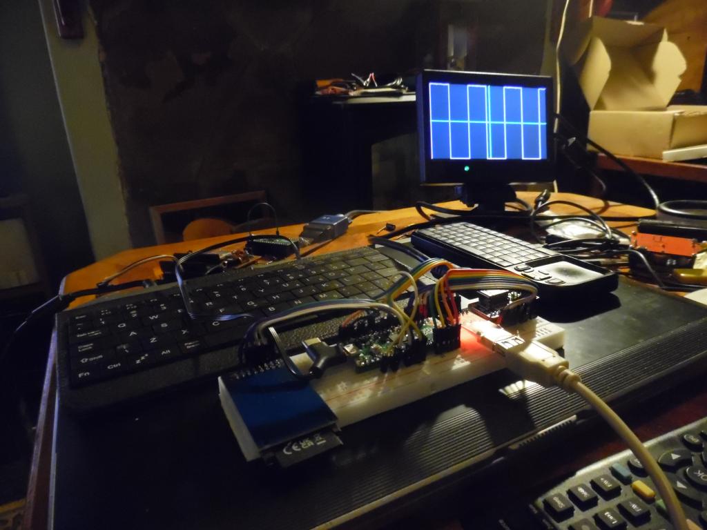 Edited 2024-11-25 08:01 by stanleyella |
||||
| The Back Shed's forum code is written, and hosted, in Australia. | © JAQ Software 2026 |
