
|
|
Forum Index : Microcontroller and PC projects : Hardware design issue
| Author | Message | ||||
| Malibu Senior Member Joined: 07/07/2018 Location: AustraliaPosts: 261 |
G'day all, I've just got my first order from JLCPCB (great service, top-notch assembly; I'm very impressed!) for my 6-channel GP Controller. A simple idea- Webmite controls 6 outputs, depending on the time settings sent through a web browser. After checking all the relevent volts from the (2x) USB connection and the rectified AC supply, I soldered in the Webmite to do some further tests. All good until I fired up the AC supply and found that the 7805 reg is getting pretty hot, plus no output is actually changing state on the ULN output. The input is changing state as expected, but not on the output drivers for the relays. Here's the (cut-down) schematic... 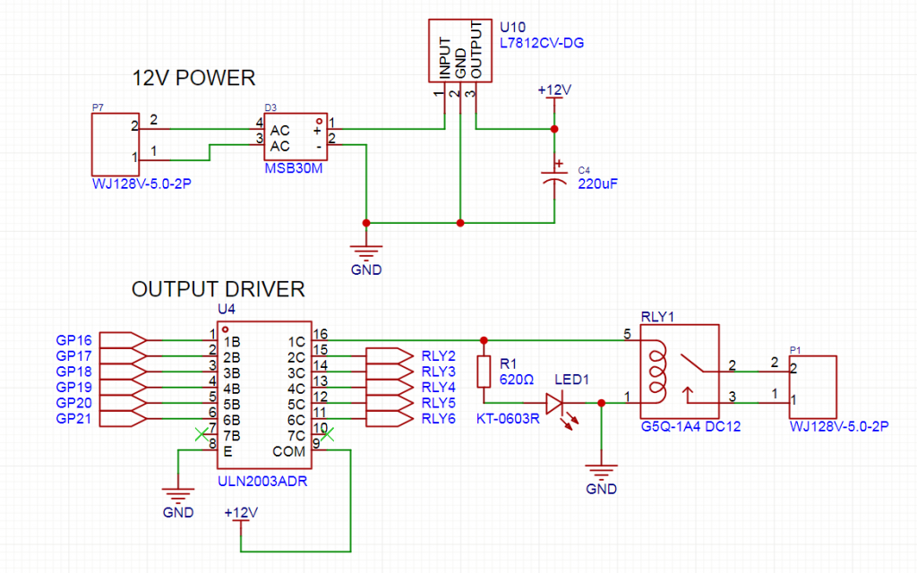 The AC comes in, gets rectified and regulated to 12VDC. That's supplied to the ULN2003 which SHOULD drive the relays accordingly (along with an LED to show the status) For some reason, the reg heats up; the LED's don't change state; nor does the relays. There's no shorts that I can find on the PCB, so I'm pretty sure the PCB is correct. Removing the relays makes no change. Do any of the hardware wizards spot whatever the dumb mistake is that I've done? It's got me a bit baffled and I'm now in head-scratch mode.......  (PS: RLY2 to RLY6 is just a repeat of the RLY1 circuit) Edited 2024-12-04 16:18 by Malibu John |
||||
TassyJim Guru Joined: 07/08/2011 Location: AustraliaPosts: 6538 |
12V goes to relays and common pin UNL2003 switches other relay leads to ground. 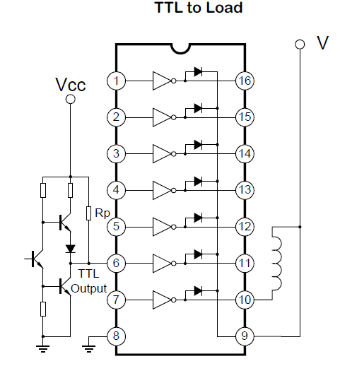 VK7JH MMedit |
||||
| PhenixRising Guru Joined: 07/11/2023 Location: United KingdomPosts: 1961 |
 Yeah, that's how I remember it  |
||||
| Malibu Senior Member Joined: 07/07/2018 Location: AustraliaPosts: 261 |
OK, so that's the dumb mistake, it seems... Shoulda pulled the relay commons high instead of low...  Live and learn, I'll make some changes tomorrow and get back to you  Thanks for the input! John |
||||
| PhenixRising Guru Joined: 07/11/2023 Location: United KingdomPosts: 1961 |
There is also the not-as-popular high-side driver, ULN2981 or MIC2981. MIC2981.pdf Edited 2024-12-04 17:08 by PhenixRising |
||||
| Mixtel90 Guru Joined: 05/10/2019 Location: United KingdomPosts: 8911 |
If you have AC in then rectify it as shown in the circuit the DC is *very, very* rough and will drop to zero on every half cycle as there is no reservoir capacitor from pin 1 of the 7812 to GND. I'd be very surprised if this power supply will work. Also, the output capacitor from the 7812 is high for those chips. Move the 220uF to the input of the regulator. That will give you about (12*1.4)-1.2= 15.5V DC. Dropout voltage on these is about 2V, so you should be ok for a 12V regulator if the current isn't too high. Normally you'd want to see around 18-19V here. Now use about 22-47uF capacitor for the output. It only really needs 0.1uF for stability, but I like a bit more for pulling relays in. Mick Zilog Inside! nascom.info for Nascom & Gemini Preliminary MMBasic docs & my PCB designs |
||||
| lizby Guru Joined: 17/05/2016 Location: United StatesPosts: 3784 |
And also, why rectify 12V AC when 12V DC power supplies are readily available with all sorts of current capacities? Where I am (North America), it's a lot easier to get a nominal 12V DC power supply than an AC supply. PicoMite, Armmite F4, SensorKits, MMBasic Hardware, Games, etc. on FOTS |
||||
| Volhout Guru Joined: 05/03/2018 Location: NetherlandsPosts: 5936 |
Hi lizby, Maybe to avoid the "wrong polarity" of the DC barrel connectors. It may not be intended for AC at all. Volhout PicomiteVGA PETSCII ROBOTS |
||||
| tgerbic Senior Member Joined: 25/07/2019 Location: United StatesPosts: 119 |
Also if you get a 12VDC supply you can eliminate the bridge and regulator. Could also use a much smaller capacitor or eliminate it. |
||||
| Mixtel90 Guru Joined: 05/10/2019 Location: United KingdomPosts: 8911 |
I'm sure that if a 12V DC supply had been available it would have been used. :) Nowadays you don't use expensive mains transformers when a SMPS is half the price. Transformers are fun. The exception is for safety or ultra low leakage applications, in which case you often also avoid toroidal transformers (the primary wires have to get out via the secondary winding) and stick to split bobbin C or EI types too. You can't beat vintage design techniques, apparently. :) Mick Zilog Inside! nascom.info for Nascom & Gemini Preliminary MMBasic docs & my PCB designs |
||||
| PhenixRising Guru Joined: 07/11/2023 Location: United KingdomPosts: 1961 |
I have several floor-units for my guitar that are fed LV-AC and in fact, all-too-frequently, someone complains that "it stopped working" and it turns out that they lost the original AC PSU and tried using a DC PSU of the same voltage.  I have toyed with the idea (but I'll never get around to it ) of adding some stuff to one of my units but I wouldn't want to add extra load to the internally rectified DC and so I would also look at separate rectification and upgrade the AC supply...so I can kinda relate to what the OP might be doing.Edited 2024-12-05 20:09 by PhenixRising |
||||
| Volhout Guru Joined: 05/03/2018 Location: NetherlandsPosts: 5936 |
Mick, I understand why. With AC input the transformer also works as a filter, and typically all you get is 50Hz/100Hz hum. Easy to workaround. Switchmode power supplied (even when switching at frequencies above 20kHz) can output audio band modulation depending on the load (cycle skip at low load) similar to the pico power supply. And typically transformers have a very loooooong lifetime. I just look at my 65 year old Philips PE4801 power supply, or my 50 year old grundig clock radio. Still have to find a switchmode power supply that comes close. My 30yr old Phillips PM3394 oscilloscope comes close though.. Volhout Edited 2024-12-05 20:57 by Volhout PicomiteVGA PETSCII ROBOTS |
||||
| Mixtel90 Guru Joined: 05/10/2019 Location: United KingdomPosts: 8911 |
You have to watch external supplies. You shouldn't connect the output of a SMPS to mains earth unless it's designed for it, for example. There is a class Y (I don't think it's X in this case) capacitor between mains earth and output negative to reduce RF emissions. Earthing the output shorts it out and the output starts to radiate RF. A low voltage AC supply can be centre tap earth and the two (fused) ends of the winding as a twisted pair to reduce radiated hum. If the earth tap is on the centre of a WW pot that's connected across the winding rather than the transformer you can tune the radiated hum down to almost nothing! . Edited 2024-12-05 21:06 by Mixtel90 Mick Zilog Inside! nascom.info for Nascom & Gemini Preliminary MMBasic docs & my PCB designs |
||||
| Volhout Guru Joined: 05/03/2018 Location: NetherlandsPosts: 5936 |
Mick, Class II or class I makes the difference. Volhout PicomiteVGA PETSCII ROBOTS |
||||
| Mixtel90 Guru Joined: 05/10/2019 Location: United KingdomPosts: 8911 |
Class X is rated to go across the supply lines, Class Y from a supply line to earth. It's the little ground cap that can give you a slight "tingle" from the low voltage output as it introduces a tiny amount of leakage. It's not a faulty supply. IIRC Class I power requires that one side of the output is connected to PE (mains earth). Class II is often called "double insulated" and there is no requirement for the output to be grounded, there is sufficient insulation from the mains. Many SMPS are of this sort, especially small ones. Then there's Class III which is extra low voltage (less than 60V) and has no requirement for earthing. It's considered to be safe to touch directly. Mick Zilog Inside! nascom.info for Nascom & Gemini Preliminary MMBasic docs & my PCB designs |
||||
| The Back Shed's forum code is written, and hosted, in Australia. | © JAQ Software 2026 |
