
|
|
Forum Index : Microcontroller and PC projects : SL6 Teardrops and curves
| Author | Message | ||||
| PhenixRising Guru Joined: 07/11/2023 Location: United KingdomPosts: 1961 |
Trivial, yes but there's just something satisfying about this: 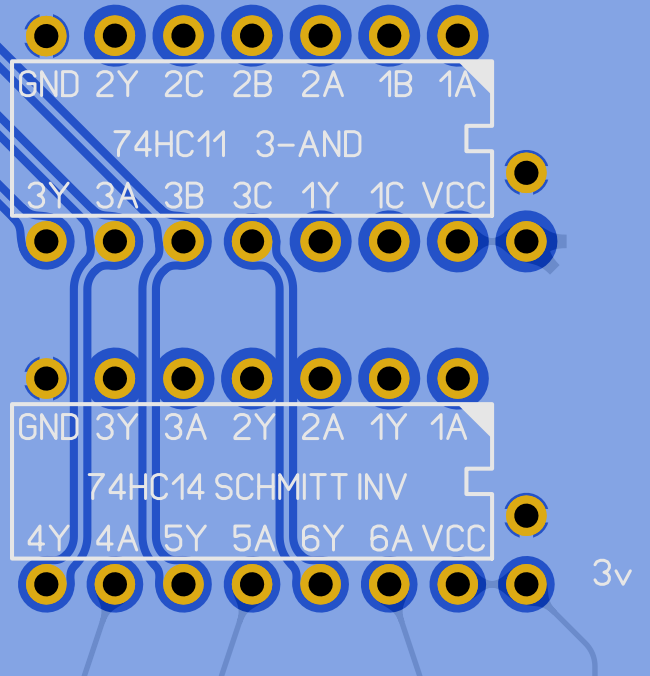   |
||||
| Mixtel90 Guru Joined: 05/10/2019 Location: United KingdomPosts: 8911 |
I tried it but we didn't get along. If you start doing things like moving traces around or deleting them once the teardrops have been applied they become a track plus two triangles, which have to be deleted separately. You can remove all the teardrops at once but not individual ones. I'm flippin' rough, me. No niceties. :) Mick Zilog Inside! nascom.info for Nascom & Gemini Preliminary MMBasic docs & my PCB designs |
||||
| PhenixRising Guru Joined: 07/11/2023 Location: United KingdomPosts: 1961 |
I went through that, Mick but I have mastered it and now it's 2nd nature. Not a hassle at all. Probably not important in this context but I just don't like abrupt transitions. Comes from machine designing, I guess. |
||||
| Volhout Guru Joined: 05/03/2018 Location: NetherlandsPosts: 5936 |
Phenix, PCB manufacturers do not like this: 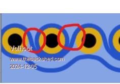 Volhout PicomiteVGA PETSCII ROBOTS |
||||
| PhenixRising Guru Joined: 07/11/2023 Location: United KingdomPosts: 1961 |
The pointy bits? Do they reject the design or do they make changes? |
||||
| Mixtel90 Guru Joined: 05/10/2019 Location: United KingdomPosts: 8911 |
Pointy bits can cause the copper to peel during etching, you tend to get bad edges. Also watch out if you are running parallel tracks and there is a miniscule area of ground plane between them - it can get etched away. In fact it usually doesn't matter, but you might be affecting the ground plane in some cases and lose a connection. Whether a design gets rejected depends on how good the checking is, I suppose. :) Mick Zilog Inside! nascom.info for Nascom & Gemini Preliminary MMBasic docs & my PCB designs |
||||
| PhenixRising Guru Joined: 07/11/2023 Location: United KingdomPosts: 1961 |
Do you use ground-planes, Mick? I see lots of boards where there aren't any. |
||||
| Mixtel90 Guru Joined: 05/10/2019 Location: United KingdomPosts: 8911 |
Almost always. Now I usually use the top layer as GND. That way it's easy to get a connection on all the components anywhere on the board, even on SMD components. I often use the top layer for 5V traces too, as they tend to be fairly large. The bottom layer can be different and I've used it in various ways. Sometimes it's good to connect it to 3V3 for easy distribution, other times GND to get round awkward bits, other times just floating (although I prefer to use it for GND if possible). I take the ground plane off on both sides where I want to put an antenna on a module or, usually, where I want to put mains-carrying components because I want electrical clearance. PCB manufacturers like ground planes as they require less etching. :) Mick Zilog Inside! nascom.info for Nascom & Gemini Preliminary MMBasic docs & my PCB designs |
||||
| Volhout Guru Joined: 05/03/2018 Location: NetherlandsPosts: 5936 |
Hi Phenix, Groundplanes contain a lot of copper. As such they are typically low impedance. And therefore it makes life for a designer a lot easier. You do not have to think about return path (star ground) that much. Except in RF and high power design. Just think about the audio equipment from the 70's and 80's. Single sided phenolic boards, cluttered with ground traces to feed everything back to the one start ground. Volhout Edited 2024-12-05 23:54 by Volhout PicomiteVGA PETSCII ROBOTS |
||||
| PhenixRising Guru Joined: 07/11/2023 Location: United KingdomPosts: 1961 |
Thanks guys...I got rid of the pointy bits  |
||||
| Mixtel90 Guru Joined: 05/10/2019 Location: United KingdomPosts: 8911 |
One should never overlook the damage that can be caused by pointy bits in the wrong places. Mick Zilog Inside! nascom.info for Nascom & Gemini Preliminary MMBasic docs & my PCB designs |
||||
| PhenixRising Guru Joined: 07/11/2023 Location: United KingdomPosts: 1961 |
 |
||||
| The Back Shed's forum code is written, and hosted, in Australia. | © JAQ Software 2026 |
