
|
|
Forum Index : Microcontroller and PC projects : DRO Display, Ardunio & Co-Pilot adventures
| Author | Message | ||||
| IanT Senior Member Joined: 29/11/2016 Location: United KingdomPosts: 130 |
I am in the process of developing a better display for my small mill's DRO set-up. They are cheap capacitive scales but came with a small monochrome LCD remote display. Apart from the difficulty (for my ageing eyes) in reading the LCD panel, it has some very indifferent membrane buttons, plus needing two CR3032 batteries. But it was cheap! My cunning plan is to replace this LCD display with a 17" VGA monitor that I have available. I am using a spare VGA PCB (the twin socket Peter M style one) with an SD card and a protoboard to attach the micro-USB connectors. I've got a dummy Mode1, Font6 (with tiles) X, Y, Z display already running and now need to decode the incoming scale signals. Once I have a basic DRO reader/display running, I can also add other functionality that the simple LCD can't provide. But first things first... I'm still determining whether they are BIN6 or iGauging 21 bit but started to think about how to write the code. Looking for a starting point, I searched for existing code (I like a leg-up) and found a BIN6 routine in Arduino.I haven't touched Arduino code much since discovering Mites about 10 years ago, so whilst I could read a good bit of it, there were parts that were unclear to me (and it wasn't commented). It was getting quite late, so on a whim, I pasted the code into Co-Pilot and asked it to "translate" into MMB. Co-Pilot immediately produced a 'clean' version of the Arduino code and (after explaing there were syntax differences between the two languages) produced the MMB version. I was gob-smcked (e.g suprised) not having used any AI before. I've seen others mention Chat-GPT (?) here before but hadn't realised how far these systems had come. I thought it might recognise the Ardunio code but really didn't expect it to know MMB. That's it, just a note from a Back Shed Lurker. I'm sure others here are well in front of me in this regard but I can now see how disruptive AI will be and that's before FSD cars and the Robots really start to arrive. I think I'm somewhat relieved to be retired these days... Regards, IanT |
||||
| Mixtel90 Guru Joined: 05/10/2019 Location: United KingdomPosts: 8911 |
So, is the code produced anything like runnable? That is the question. :) Mick Zilog Inside! nascom.info for Nascom & Gemini Preliminary MMBasic docs & my PCB designs |
||||
| IanT Senior Member Joined: 29/11/2016 Location: United KingdomPosts: 130 |
The DRO scale bodies are connected to the negative side of the battery Mick, which apparently indicates that they are probably either BIN6 or 21 Bit based, rather than the other Chinese DRO (24 Bit etc) O/P standards. My understanding is that the BIN6 scales send signals to the display without an external clock but last night I couldn't see anything on the output cable with a simple meter or scope examination, so it may not be BIN6. The 21Bit (iGauging) sensor needs the display to send it a clock signal before it responds, so I'm going to rig-up two back-to-back micro-USB connectors on a protoboard, so that I can see what is happening between the LCD display and the DRO scale when connected together. The scales do work with the LCD display of course... So to answer your question. No, I don't know if the MMB BIN6 code actually works (and I may not need it now) but it is certainly easier for me to read and debug MMB, than Arduino code. I'm not a skilled programmer, everything takes time very often because of my own silly mistakes. Adapting the Arduino code to MMB would have taken me a while. So anything that gives me a running start and saves me time with a new (and unfamiliar) problem is very welcome. I've just (now) found some code that may be good for 21 Bit scales but I want to see something happening on a scope before I go too much further with the software side. My Manager has other plans for me this afternoon but hopefully I'll make a bit more progress this evening. I'll certainly be trying Co-Pilot again and I'll let you know how I get on. Regards, IanT |
||||
| Mixtel90 Guru Joined: 05/10/2019 Location: United KingdomPosts: 8911 |
Thanks Ian. Can you guess what percentage of all this I actually understood? lol One of my friends asked ChatGTP to write a program in MSX BASIC (I must admit that this was some time ago and things have moved on a bit). The result was (relatively) valid GW-BASIC that had no chance of running on a MSX machine. Translation has improved since, and I'm intrigued that a LLM might at some point be able to convert Arduino to MMBasic, taking account of the library functions. Mick Zilog Inside! nascom.info for Nascom & Gemini Preliminary MMBasic docs & my PCB designs |
||||
| CaptainBoing Guru Joined: 07/09/2016 Location: United KingdomPosts: 2171 |
I have dabbled with GPT producing code and I found that you nearly lways have to have a pretty good guess at what to expect in order to check its ouptut which is frequently buggy and it downright lies and makes stuff up. beware as an aside, MMBasic is a pretty good fit for VB6 and I often ask for translations etc in VB6 using no external libraries or modules only primitives. That work... of course there are language differences (integers Vs Longs springs to mind) but it usually results in a chunk of code that is fit for a search & replace in Notepad++ h |
||||
| IanT Senior Member Joined: 29/11/2016 Location: United KingdomPosts: 130 |
A quick update. I built the protoboard USB rig tonight to have a look at the signal flow between the DRO and LCD Display. A combination of noise and my lack of skill (I seem to have forgotten everything I once knew about using a scope) slowed progress quite considerably. I eventually re-rigged things and the noise improved but synching was still a problem. It finally dawned on me to dig out a second scope probe and use the clock line to synch on the signal line. 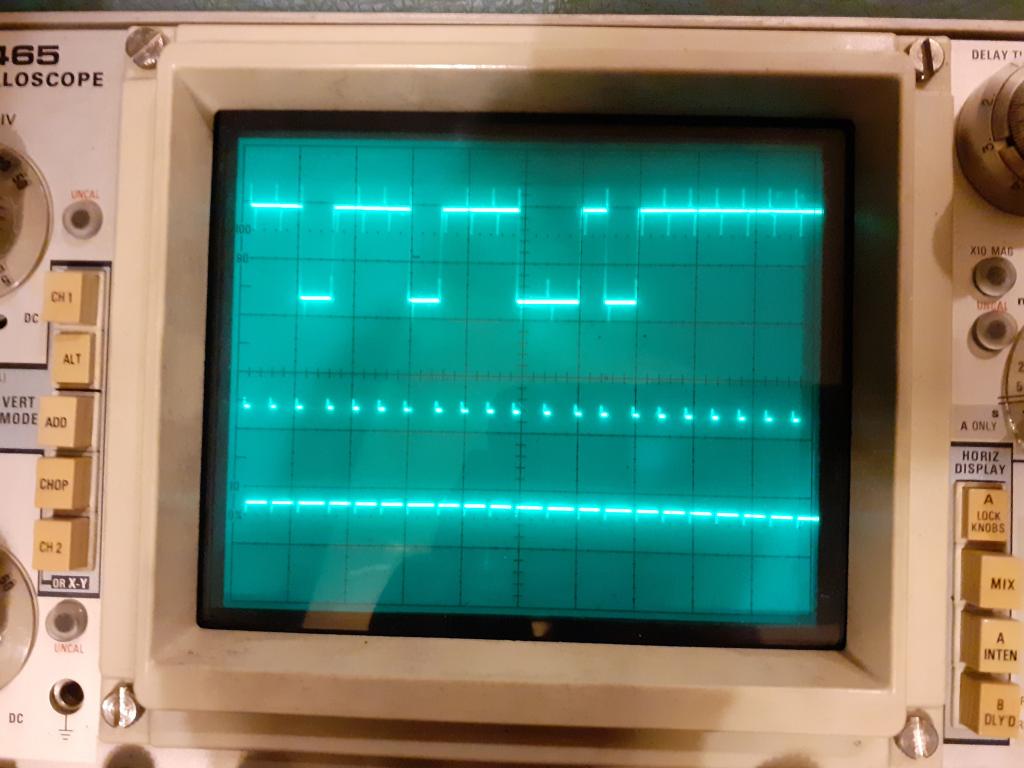 So, there it is, a 21 Bit clock signal that runs for 2ms, followed by a 4ms gap. The data signal occurs during the clock period. So I now have something to work with on the software side. The iGaging 21Bit Arduino code should therefor be a good starting point but I'm sorry to report that (as you both expected I think) the CoPilot MMB translation isn't going to to work out the box, although there is probably still a helpful framework there for me to work on. That's for another night now though. Regards, IanT |
||||
| phil99 Guru Joined: 11/02/2018 Location: AustraliaPosts: 3293 |
The clock noise on the data line is actually helpful here. Makes it easy to see that you read the data on the falling edge of the clock. |
||||
| IanT Senior Member Joined: 29/11/2016 Location: United KingdomPosts: 130 |
Easy for you maybe Phil :-) But yes I should have enough information now to figure out how to make this work. I only have 2 axis to read (at the moment) but the fact the iGaging scales only respond to the display clock makes life a bit easier I think. We'll see. You may not be hearing any updates for a while. I may also suffer considerable hair loss in the process... Regards, IanT |
||||
| PhenixRising Guru Joined: 07/11/2023 Location: United KingdomPosts: 1961 |
I have come across some who are using Perplexity ai for coding assistance and so I asked Perplexity itself about its suitability. It recommended Phind which reminded me that I had a good experience with this in the past....but forgot about it. Edited 2025-01-05 20:12 by PhenixRising |
||||
| The Back Shed's forum code is written, and hosted, in Australia. | © JAQ Software 2026 |
