
|
|
Forum Index : Microcontroller and PC projects : A selfmade breadboard friendly HDMI plu
| Author | Message | ||||
| dddns Guru Joined: 20/09/2024 Location: GermanyPosts: 891 |
Hello :) This ended now in prototyping and building a showcase. It was not my intention and I could not completely foresee, that it would fit that well.. I mean the whole outcome: It is ALL pin out, really all! I could easily solder the remaining probe connections to the lower row to make it complete and I would bring GP1 as high freq input to the outside. It is very robust and compact and offers everything I can think of. The audio could be replaced by a I2S, the space is sufficient. The PGA2350 is a great design for me. All kind of firmwares available for 2350 can be used and make sense and is suitable for almost every interest. This is again dedicated to us all. Take one or the other idea maybe and I hope again that I could give some inspiration. It was also my way trying to contribute.. All the best to All of you! :) |
||||
| dddns Guru Joined: 20/09/2024 Location: GermanyPosts: 891 |
Just a concept and it's all about the form factor and versatility. I've seen now all work from everybody. It's an old keyboard for oldschool pads but feels like a lenovo. I will make it completely foldable. I took the time and made it work in full extend and the audio sounds and works superb!! Cheers! 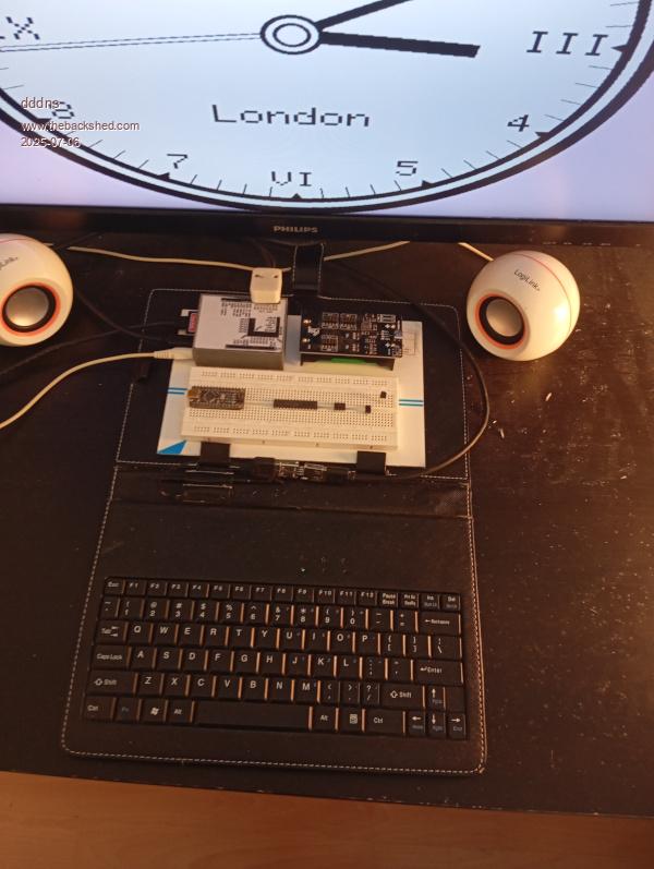 |
||||
| stanleyella Guru Joined: 25/06/2022 Location: United KingdomPosts: 2807 |
 great great |
||||
| dddns Guru Joined: 20/09/2024 Location: GermanyPosts: 891 |
Hello again :) I have said this is my last tinkering..don't know but I wanted to finish that. The build works really excellent stable, the audio quality is very nice. So here is the last? chapter. I have drawn a layout some days ago and I will finish this in the way I started. I don't design first and then do it but while I'm drawing the first print is already running :)) Many people have many different thoughts what could be done with PicoMite, here are mine. This could be an educational platform or just for fun. It is all pinout, all firmware and multipurpose :) PGA2350, SD, Audio, RTC, USB, Hub, ILI9341, HDMI and VGA. I'll make it switchable. It's A5 size, the paper underneath is A4. 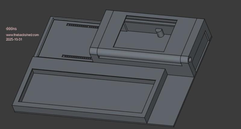 pico_lab_freecad.zip Reality: 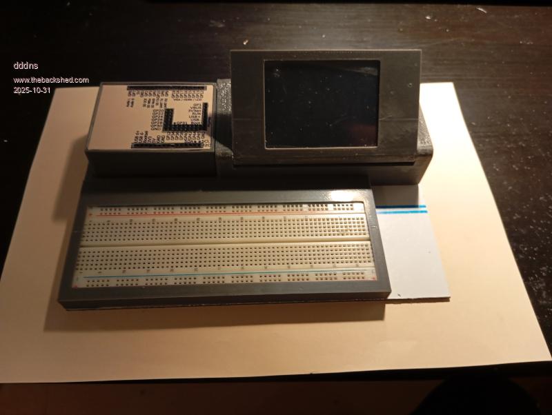 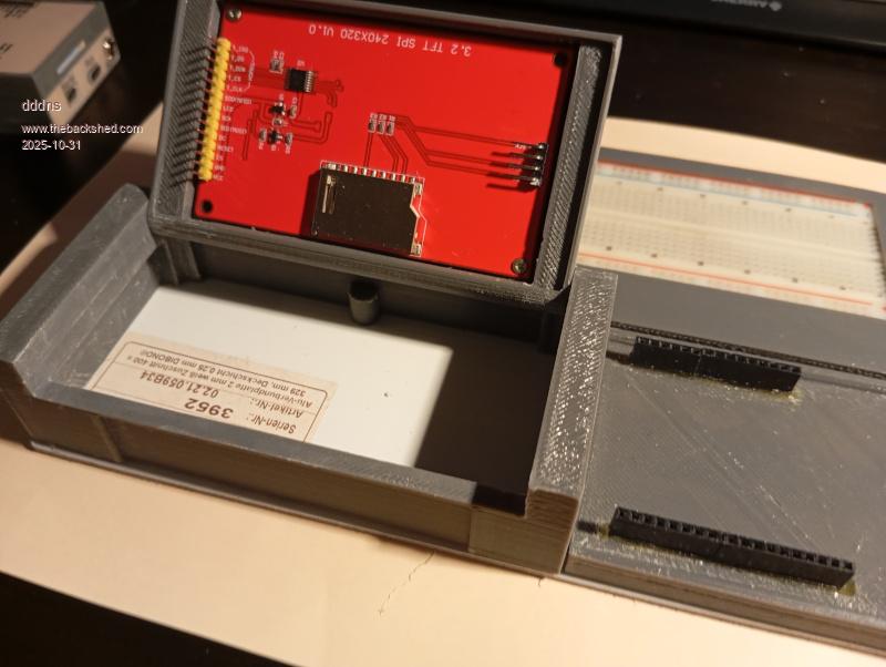 Edit: the free space on the right needs to be filled..thoughts? :) Edited 2025-10-31 04:37 by dddns |
||||
| dddns Guru Joined: 20/09/2024 Location: GermanyPosts: 891 |
This is my latest work on this. The layout for the breadboard part is completely reworked.. The last parts I found are some 20year old switches I used for a Linux project which I have torn apart. The grey is empty and I'll use last few meters of black. Mad Max from the scratch..I'll try to get it done :) 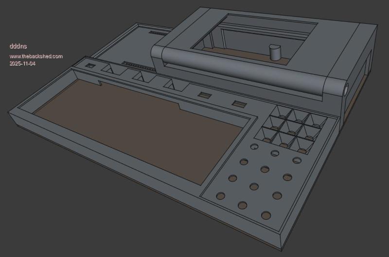 pico_lab.zip 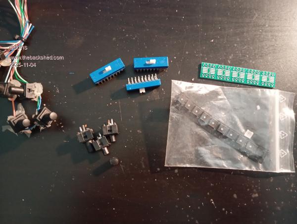 Switches are 6x on/on fromAugat |
||||
| dddns Guru Joined: 20/09/2024 Location: GermanyPosts: 891 |
First print I've done was for the bin. The corners came up and it warped. Too bad this was in black and I started today a new try. Because this material is shrinking so much I printed it on a cold bed but with PU tape underneath and the first layer with 235°C quite hot. This stuck real good together and I got an absolutely plain part in the end. I filled the pockets for the acrylic cover before printing and milled it out after: 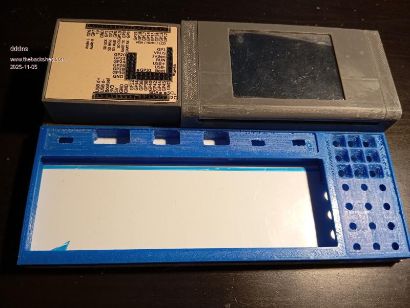 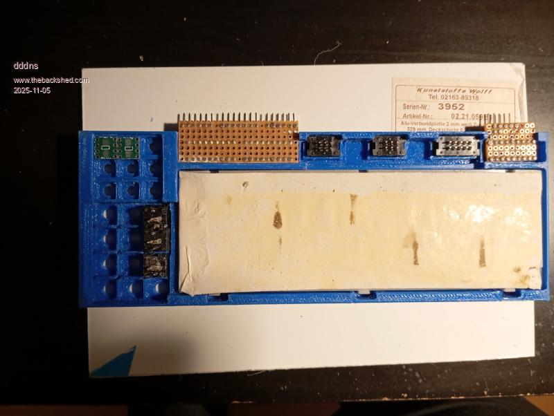 |
||||
| dddns Guru Joined: 20/09/2024 Location: GermanyPosts: 891 |
Hello :) I decided to turn around the display and the holder by rotating the the parts at their base feature and adjusting the offset: 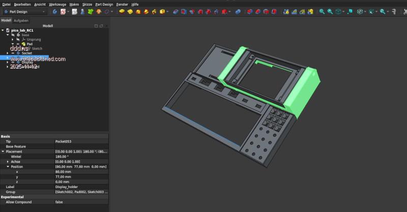 Updated like it is now: pico_lab.zip First I fitted in the acrylic and then build it up. Of cause a 3x3 matrix would cost 1,50 and having all on carrier pcb's would be much nicer.. So I build it in early 80's style :) 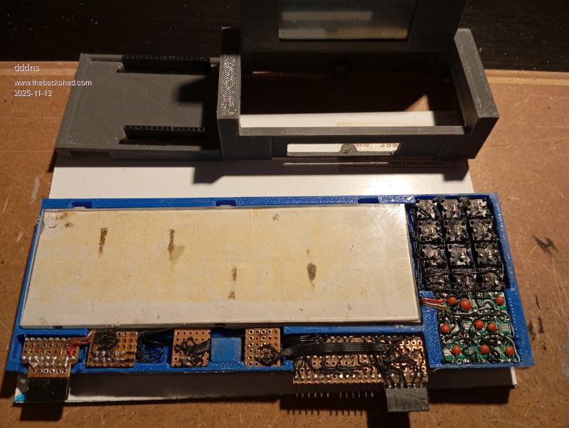 With labels it will get a different look..that's next. The height is exactly 12mm: 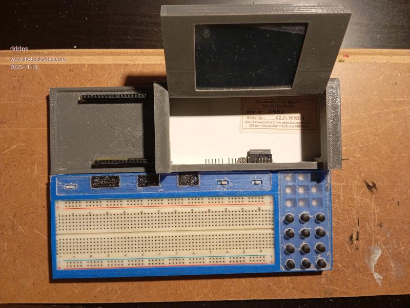 |
||||
| dddns Guru Joined: 20/09/2024 Location: GermanyPosts: 891 |
Starting a project is easy and finishing it is always hard :)) Finished and tested all all components 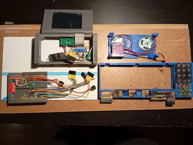 I limited the maximum volume and play tone 500,500 at 100% volume takes 150mA 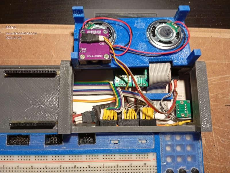 All USB sockets are power supplied by the hub. The input of the hub can be connected wheter to the Pico or to the external USB-C socket and can be used stand alone. 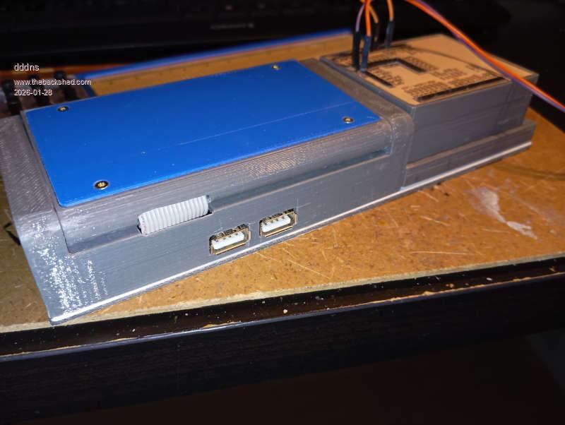 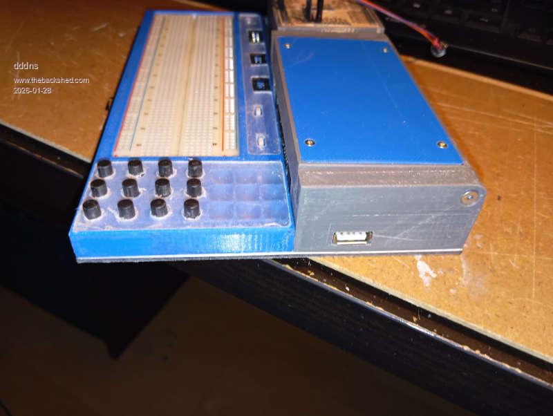 It runs excellent with the latest firmware 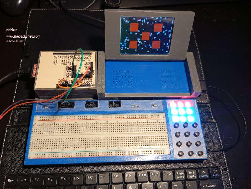 option list PicoMite MMBasic USB RP2350B Edition V6.02.00 OPTION SERIAL CONSOLE COM2,GP8,GP9 OPTION SYSTEM SPI GP2,GP3,GP0 OPTION LCD SPI GP14,GP15,GP12 OPTION SYSTEM I2C GP4,GP5 OPTION FLASH SIZE 16777216 OPTION COLOURCODE ON OPTION KEYBOARD US OPTION PICO OFF OPTION CPUSPEED (KHz) 378000 OPTION LCDPANEL CONSOLE 7 OPTION DISPLAY 30, 53 OPTION LCDPANEL ILI9341BUFF, LANDSCAPE,GP16,GP17,GP18 OPTION TOUCH GP13,GP19 GUI CALIBRATE 0, 3925, 3875, -902, -656 OPTION SDCARD GP10 OPTION AUDIO GP6,GP7', ON PWM CHANNEL 3 OPTION RTC AUTO ENABLE OPTION DEFAULT FONT 7, 1 |
||||
| Volhout Guru Joined: 05/03/2018 Location: NetherlandsPosts: 6008 |
Hi dddns, Yes, that always catches one. The famous 80/20 rule. In 20% time you get the first 80% done, but then it takes 80% time for the last 20%. Good to see it is finished. Now you can start your hardware experiments. On photo's the 3D printed parts look a bit rough. To make it posh, you could give it a spray-paint (rattle can). I hope this tool serves you well. Volhout PicomiteVGA PETSCII ROBOTS |
||||
| dddns Guru Joined: 20/09/2024 Location: GermanyPosts: 891 |
This is made with parts I had and this very old and ugly PLA was my last material. Instead of painting I would rather re-print it in ABS including all these hand made corrections. I hope it will look better once all the labels are done.. |
||||
| dddns Guru Joined: 20/09/2024 Location: GermanyPosts: 891 |
Last pictures for this issue to complete it.. 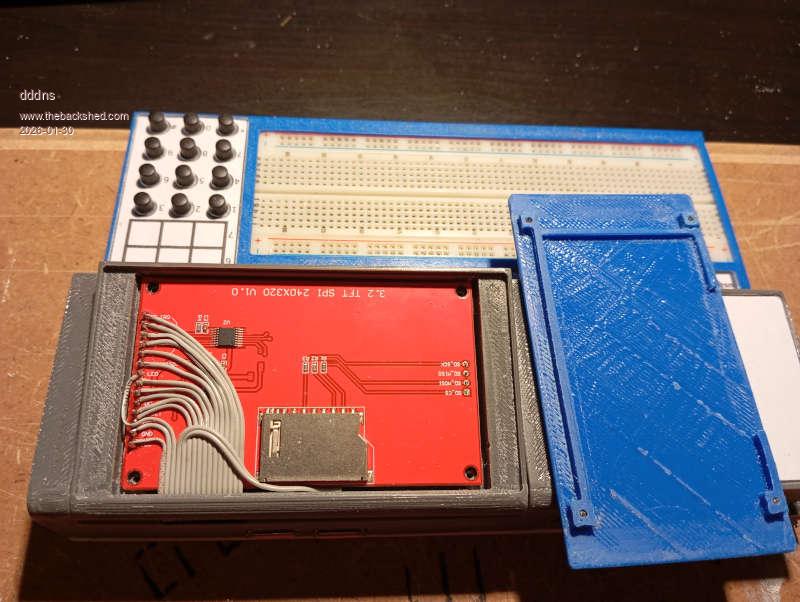 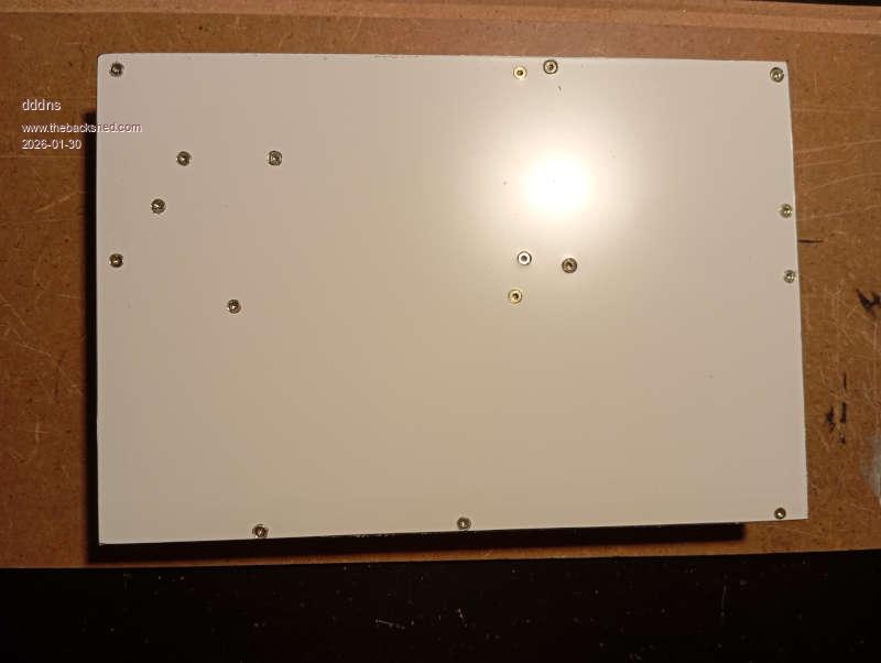 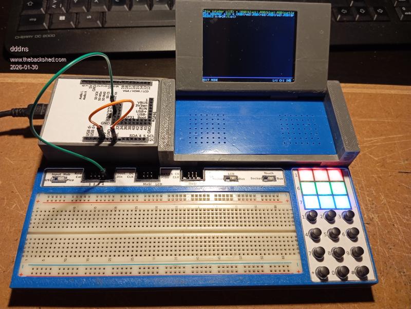 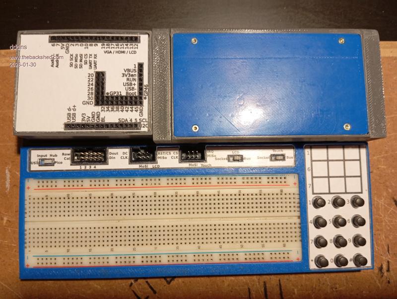 |
||||
| The Back Shed's forum code is written, and hosted, in Australia. | © JAQ Software 2026 |
