
|
|
Forum Index : Microcontroller and PC projects : Component Tester - how does it test LEDs
| Author | Message | ||||
| Nimue Guru Joined: 06/08/2020 Location: United KingdomPosts: 427 |
I have one of these cheapo component testers: 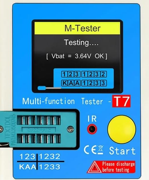 As I recycle many of my old parts and things I salvage from dead stuff, I use it a fair bit. Two questions: (1) How does it test LEDs? Clearly it must ramp up the voltage and measure the current flowing through the LEDs. If I was doing it manually I would plot something like: 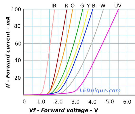 The point the LED is "on" would be the first part of the linear portion of the graph. Beyond that, the LED is "on" but just getting brighter. I guess that for each step in voltage it calculates the difference in current levels. In the linear portion, that difference would be constant each time the voltage ramped up. Checking that my understanding is correct or if there is another way. (2) Say I wanted to create a similar device (and say its limited to LEDS) - how would I wrangle the a 'mite to create an output of voltages? A potential divider/variable resistor would work manually, but what are the options for creating a variable voltage output? Is there an IC for that? N Entropy is not what it used to be |
||||
| phil99 Guru Joined: 11/02/2018 Location: AustraliaPosts: 3293 |
The odds are it doesn't go to that much trouble. My guess is it just has a series resistor driven by a Dout pin and an Ain pin to read the voltage. A look-up table to sat what voltage is what colour. For a variable output voltage high frequency PWM and a filter will do the job. |
||||
| Mixtel90 Guru Joined: 05/10/2019 Location: United KingdomPosts: 8911 |
It uses a resistor in series with the supply and monitors the voltage across the LED. When you put an LED into the socket the display will indicate Vf for the LED while the resistor limits the current through it. LEDs are current-operated devices. The voltage across them (Vf) remains more or less constant as the current changes. They probably aim for about 5mA through the LED, but it could be anything from 1mA up to 20mA for small LEDs. Power LEDs will accept a lot more. Mick Zilog Inside! nascom.info for Nascom & Gemini Preliminary MMBasic docs & my PCB designs |
||||
mclout999 Guru Joined: 05/07/2020 Location: United StatesPosts: 509 |
Does anyone know what the GitHub for it is? I think it's open source. Edited 2025-06-10 06:35 by mclout999 They call me Shai-Hulud (The maker) |
||||
| The Back Shed's forum code is written, and hosted, in Australia. | © JAQ Software 2026 |
