
|
|
Forum Index : Microcontroller and PC projects : Yet another minimal Pico system for MMBasic :)
| Author | Message | ||||
| Mixtel90 Guru Joined: 05/10/2019 Location: United KingdomPosts: 8911 |
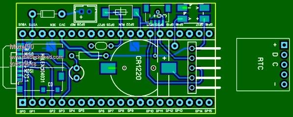 Just a design idea. You can get 3 of these out of a 100x100mm board. Not recommended for the W versions as the antenna is a bit close to other stuff. However, it should work with any other pin-compatible Pico clone, including the YD-RP2040 as pins 39 and 40 can be linked. This should also allow it to work with a USB hub. I don't think I'd like to use HDMI with it but it might work. The RTC is the tiny self-contained module that plugs onto the end if you want it. My usual idea, that you can fit an external battery when the little yellow one dies. JST 2 connector for a backup battery. QWIIC (if you ever use them - I never have). Depends on the RTC for pullups. WS2812 on the not much use GP22, however you can break a solder blob link to disconnect it and run a wire link from a pad to TP5 to run it from GP25 so that it doesn't use any pins. Obviously, it's not supported by Heartbeat so that has to be disabled. GP0-GP3 used for SD card GP20 & GP21 used for I2C GP22 used for WS2812 (but see above) You get all the rest. :) Mick Zilog Inside! nascom.info for Nascom & Gemini Preliminary MMBasic docs & my PCB designs |
||||
| PhenixRising Guru Joined: 07/11/2023 Location: United KingdomPosts: 1961 |
You just can't stop playing with SL6  I'm the same. Really want to start using EasyEDA but this thing is sooo therapeutic.  |
||||
| Amnesie Guru Joined: 30/06/2020 Location: GermanyPosts: 757 |
What is SL6 and is it free? Most of the time I am using easyEDA - I really like it. Greetings Daniel Edited 2025-06-18 23:43 by Amnesie |
||||
| PhenixRising Guru Joined: 07/11/2023 Location: United KingdomPosts: 1961 |
Sprint Layout 6 For direct laying-out PCBs. Once you get the hang of it, you're hooked. |
||||
| PhenixRising Guru Joined: 07/11/2023 Location: United KingdomPosts: 1961 |
I have the plug-in for curved traces and teardrop pads: 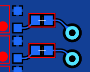 |
||||
| Mixtel90 Guru Joined: 05/10/2019 Location: United KingdomPosts: 8911 |
No, SL6 isn't free, unfortunately. If you want something free get EasyEDA. It's a much more capable package for PCB design. However, SL6 can be used to design a lot more than PCBs. It's more of a 2D CAD package in some ways. It's dead easy to create your own "macros", like blocks. Mick Zilog Inside! nascom.info for Nascom & Gemini Preliminary MMBasic docs & my PCB designs |
||||
| JanVolk Guru Joined: 28/01/2023 Location: NetherlandsPosts: 379 |
Mick, I have those RTC modules too. The disadvantage is that the rechargeable yellow battery is empty quite quickly. The cell is charged via one of the pullup resistors of the I2C. What I did is use the NC pin on the print for an external battery connection of 3V. Then the batt. pin of the chip must first be disconnected from the print and a loose wire must be connected to the NC pin. This works fine for me. And you can also mount a standard 3V button cell with holder under the print and then it is quite simple to replace. Greetings, Jan. |
||||
| PhenixRising Guru Joined: 07/11/2023 Location: United KingdomPosts: 1961 |
I'm using the DS1307 but without the crystal. I just need non-volatile memory for a production counter. But I'm using a CR123 battery for longevity. Got a cool battery holder from AliEexpress. |
||||
| Mixtel90 Guru Joined: 05/10/2019 Location: United KingdomPosts: 8911 |
That's more or less what I do, Jan. :) I just take the battery off and loop battery + round to the NC pin. I have a couple of modules without the built-in battery now. I also have one with a 1220 holder superglued on top of the chip... Mick Zilog Inside! nascom.info for Nascom & Gemini Preliminary MMBasic docs & my PCB designs |
||||
| JanVolk Guru Joined: 28/01/2023 Location: NetherlandsPosts: 379 |
A standard Raspberry Pi Pico RP2040 with a standard sdcard mounted above the debug holes data and clk as support. Omit the middle pin. The debug pins are decoupled. Furthermore, the sdcard has been made a bit narrower so that it fits between the pins. Be careful not to make it too narrow otherwise the lid will come loose. All wiring fits under the sdcard holder, only the 3V3 is a bit off. OPTION SDCARD GP19, GP10, GP11, GP12 By using long pins such as with the Olimex print, a VGA connector hole print can be mounted on pins 13 to 18 (2x4 pins). Bend the VGA pins to 0.1 inch. See also my pdf on the forum. OPTION VGA PINS GP13, GP15. This makes it a compact PicoMite VGA USB after some fitting and measuring. Greetings, Jan. |
||||
| The Back Shed's forum code is written, and hosted, in Australia. | © JAQ Software 2026 |
