
|
|
Forum Index : Microcontroller and PC projects : doh moment
| Author | Message | ||||
| stanleyella Guru Joined: 25/06/2022 Location: United KingdomPosts: 2807 |
I tried a ili9341 board I built and upgraded to pico2 but no display so upgraded to v6.02 and set options but no display. swapped display, same. reflashed and heartbeat flashing but same. Then I realised I put the pico board wrong way round. amazed pico not damaged. how to waste hours :) 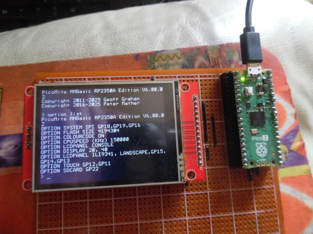 |
||||
| Amnesie Guru Joined: 30/06/2020 Location: GermanyPosts: 757 |
Ha! I know that! But I am amazed how sturdy the pico is, because I abused my picos also massivly. I mean it! Put accidently 20 Volts on the GPIO input, still works without any problems. Other time I reversed the power supply voltage (Vsys) and GND for approx. one minute! The RP-chip got hot... BUT: works without problems! Of course I marked those chip with an permanent marker as "MAYBE DAMAGED" to be sure.. but those Picos are really strong! Greetings Daniel |
||||
| stanleyella Guru Joined: 25/06/2022 Location: United KingdomPosts: 2807 |
yeah @Mnesiea.. I forgot your name. I'm no good at jokes. but rpi pico 2 is forgiving. hdmi took my attention but want to relearn lcd picomite gui cos it's really well implemented with brill features. not as good as hdmi or vga cos it's spi and slower reading the screen and stuff but still impressive imho |
||||
Grogster Admin Group Joined: 31/12/2012 Location: New ZealandPosts: 9975 |
Easy mistake to make.  Glad you worked it out, without loosing too much sanity.  Also, thanks for posting this thread. I like to also post threads where I have made a school-boy mistake, as it is light entertainment for the other members, but also a reminded that no-one is perfect, and we ALL make mistakes - sometimes very obvious silly ones! "You're only Human. You're SUPPOSED to make mistakes." - Billy Joel Smoke makes things work. When the smoke gets out, it stops! |
||||
| stanleyella Guru Joined: 25/06/2022 Location: United KingdomPosts: 2807 |
@Grogster- yeah very stupid of me. swapping displays with a working board and head scratching. the board takes 2 sizes ili9341 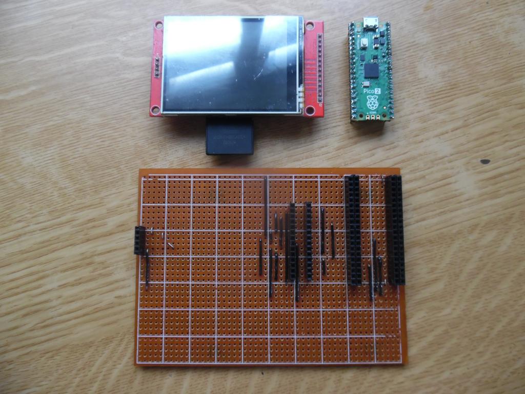 |
||||
| stanleyella Guru Joined: 25/06/2022 Location: United KingdomPosts: 2807 |
I did a ili bigger display but wired the pico upside down so I could see the gpio labels.2040 silly. got to wire diode and resistor for it to work touch and sd card which I done but not on above board and it doesn't mess with ili9341 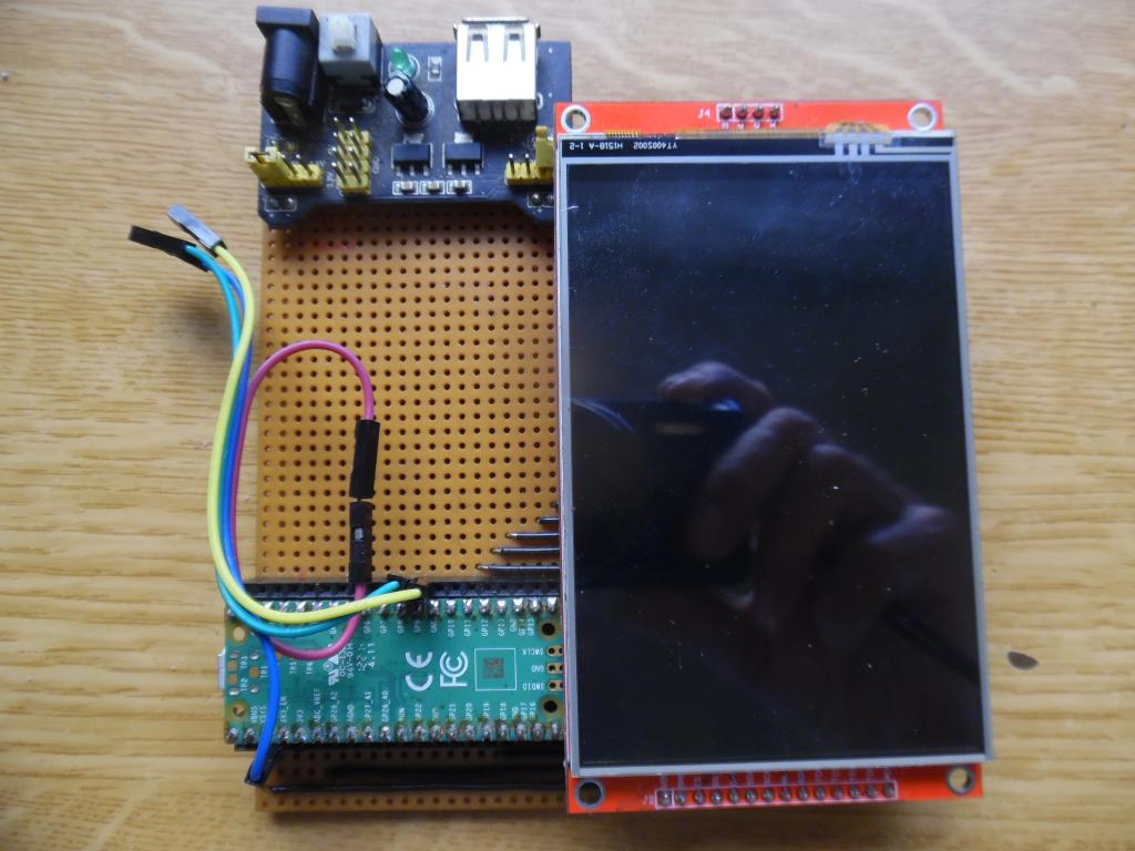 |
||||
| stanleyella Guru Joined: 25/06/2022 Location: United KingdomPosts: 2807 |
doh moment 2 the above board 2040 I decided to update to latest firmware and took the board which was usb and pressed the boot button and then plugged the usb cable. windows went bing bong then the pico board got too hot to hold. guess it was still in usb mode. and looking at the above display it has diode sdo -->:--tp0 and 10KR cs---[10k]---tp0 which isn't mentioned in the manual so is it still needed? the burning out pico is strange if it still in usb then no apply usb lead but I pressed the boot button |
||||
| phil99 Guru Joined: 11/02/2018 Location: AustraliaPosts: 3293 |
? tp0 ? I assume you mean T_DO which is Touch_DataOut and goes to Pico MISO. For an ILI9488 the diode and resistor are still needed for Blit, Image Save etc. As you have noted if they are fitted an ILI9341 will still work properly. As for the burning out Pico that sounds like reverse polarity or excessive voltage on the 3.3V supply. Perhaps for USB versions it may be better to unplug the Pico from the board before updating the firmware. That way there can be no conflict with external voltage supply. |
||||
| Volhout Guru Joined: 05/03/2018 Location: NetherlandsPosts: 5931 |
Hi Stan, I like you double row sockets for the pico. That saves board estate, and is very easy to implement. Volhout PicomiteVGA PETSCII ROBOTS |
||||
| Mixtel90 Guru Joined: 05/10/2019 Location: United KingdomPosts: 8911 |
The Boot button goes to the flash chip so pressing that doesn't have any effect on the RP2350. The data from the USB goes into the RP2350 and, yes, you do program even a USB Pico in the same way, over USB and using the Boot button. In fact, it's the only way. :) If the Pico got hot it was for some other reason than programming it. Mick Zilog Inside! nascom.info for Nascom & Gemini Preliminary MMBasic docs & my PCB designs |
||||
| Marcel27 Senior Member Joined: 13/08/2024 Location: NetherlandsPosts: 104 |
This Chip and board is designed for young kids and dumb old man. |
||||
| stanleyella Guru Joined: 25/06/2022 Location: United KingdomPosts: 2807 |
The pico is 2040 and mounted upside down to usual and had to remove it to access boot button. it was usb version and pressed boot button then connected usb lead to win pc, it created the pico drive for flashing but pico got hot around usb socket. the usb pc lead is fine. what would happen if connect powered usb from pc to usb pico? |
||||
| Mixtel90 Guru Joined: 05/10/2019 Location: United KingdomPosts: 8911 |
Yes, you can use the PC supply. In fact, that's the right way - you should disconnect any other supplies while flashing the chip. You don't know if there's a ground voltage difference between the PC and your external supply. Who am I to argue, Marcel? Signed - Dumb old man. :) Edited 2025-07-12 00:55 by Mixtel90 Mick Zilog Inside! nascom.info for Nascom & Gemini Preliminary MMBasic docs & my PCB designs |
||||
| stanleyella Guru Joined: 25/06/2022 Location: United KingdomPosts: 2807 |
mmbasic is for dumb old men |
||||
| stanleyella Guru Joined: 25/06/2022 Location: United KingdomPosts: 2807 |
I used 2 20 pin sockets but also used dual 20 pin sockets. 80 solder pins. I use headers so I can wire under pico but would not solder pico as not easy to remove. I not pcb user, it strip board, it does work :) |
||||
| The Back Shed's forum code is written, and hosted, in Australia. | © JAQ Software 2026 |
