
|
|
Forum Index : Microcontroller and PC projects : Question about PIO DMA TX interupt
| Author | Message | ||||
| AlbertR Senior Member Joined: 29/05/2025 Location: GermanyPosts: 107 |
I make some tests with the Picomite PIO for the WS2812-Output. Because the implemented function "Device WS2812" is blocking during output-time, I was looking for an other possibility. The PIO should be a candidate. Option EXPLICIT Option DEFAULT NONE Dim integer leds(255) Dim integer pack(127) Dim integer Busy = 0'as Mutex: ready to send SetPin gp22,pio1 ' The PIO program - PIO WS2812 driver on GP22 -------------------------------- ' ____ ________ '(0) __| |______ (1) __| |__ ' .2us .4us .6us .2us .8us .2us PIO CLEAR 1 PIO ASSEMBLE 1, ".program leds" PIO ASSEMBLE 1, ".line 0" PIO ASSEMBLE 1, "SET PINDIRS, 1" PIO ASSEMBLE 1, ".wrap target" 'steps |delay PIO ASSEMBLE 1, "OUT x, 1 " '1 lo 0.2us PIO ASSEMBLE 1, "SET PINS, 1 [1]"'2 hi 0.4us PIO ASSEMBLE 1, "MOV PINS, x [1]"'2 data 0.4us PIO ASSEMBLE 1, "SET PINS, 0 " '1 lo 0.2us PIO ASSEMBLE 1, ".wrap" '6 sum 1.2us = 833kHz PIO ASSEMBLE 1, ".end program list" Dim integer ExeC = Pio(execctrl GP22,Pio(.wrap target),Pio(.wrap)) Dim integer PinC = Pio(pinctrl 0,1,1,,,gp22,gp22) Dim integer ShiC = Pio(shiftctrl 0,24,0,1) 'Set Auto Pull at 24bits Dim integer Freq = 5000000 '5MHz -> 1 step -> 0.2us 'setup the machine. PIO init machine 1,0,Freq,PinC,ExeC,ShiC,0 'init Math set &hf0,leds()'all blue 'test-pattern leds(0)=&hcdabef <<8 leds(1)=&h341256 <<8 leds(2)=&haaaaaa <<8 leds(3)=&h555555 <<8 'main loop Do Pause 100 'simulate some calculation with leds() Do :Loop While Busy 'wait for ready Memory pack leds(),pack(),256,32 'copy and pack Busy = 1 'set busy-flag PIO DMA TX 1,0,4,pack() ',FinI Pause 1 PIO stop 1,0 PIO init machine 1,0,Freq,PinC,ExeC,ShiC,0 Busy = 0 'ready to start 'OutL() Loop'end main End 'subs/functions ------------------------------------------------------------- Sub FinI 'stop the PIO and re-init for next run Pause 1 PIO stop 1,0 PIO init machine 1,0,Freq,PinC,ExeC,ShiC,0 Busy = 0 'ready to start End Sub Sub OutL Local integer i=0 PIO start 1,0 'start the PIO Do While i < 4 PIO WRITE 1,0,1,leds(i) Inc i Loop PIO stop 1,0 'stop the PIO End Sub For testing the PIO-program I use the "PIO WRITE" command, DMA with interupt and with Pause. Thats the results: 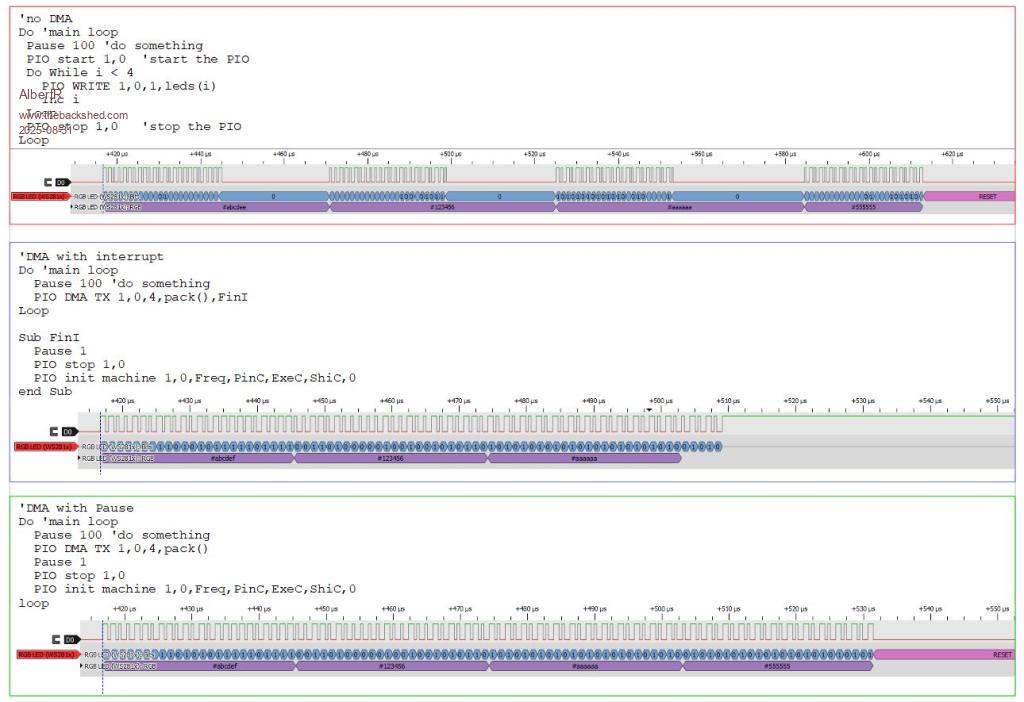 1. PIO WRITE always kills the last bit. If CPUSPEED is only 150MHz it generates a "Break" 2. PIO with TX-DMA works very good but if I use the Ready-Interupt it stops the PIO, even if there is some data left in the OSR and even if there is no PIO STOP in the sub. 3. The version with "pause 1" works spable, but then I am blocking again. That is not what I expected when I use DMA. I think I am not the only one who use PIO. Where did I thing wrong? Greetings Albert |
||||
| AlbertR Senior Member Joined: 29/05/2025 Location: GermanyPosts: 107 |
Ok, a non blocking solution could be, using a Timer-Interupt with precalculated delay. 'Do 'main loop Do ' do something Do : Loop While Busy 'wait for ready Memory pack leds(),pack(),1024,32 'copy and pack Busy = 1 'set busy-flag PIO DMA TX 1,0,1024,pack()',FinI SetTick 29,FinI,1 ' 29us/24bit Loop End 'subs/functions ------------------------------------------------------------- Sub FinI 'stop the PIO and re-init for next run SetTick 0,FinI,1 PIO stop 1,0 PIO init machine 1,0,Freq,PinC,ExeC,ShiC,0 Busy = 0 'ready to start End Sub But is this the right way/solution? Albert |
||||
| matherp Guru Joined: 11/12/2012 Location: United KingdomPosts: 11645 |
PIO DMA TX waits before firing the interrupt until the fifo is clear. It can't know the status of the OSR or any other PIO internals so there is no way it can wait until the PIO finishes before stopping the processing. Your workaround is probably as good as it gets. When the PIO is running a faster process then the inherent delay in the MMbasic interrupt firing masks the issue. |
||||
| AlbertR Senior Member Joined: 29/05/2025 Location: GermanyPosts: 107 |
Thanks for the quick answer. I already thought to myself that the FIFO clear is the trigger, but why did the PIO stops by calling the Interupt. In the examples from the manual there is an additional "PIO STOP"? A "pause 1" before it has no effect. Albert |
||||
| AlbertR Senior Member Joined: 29/05/2025 Location: GermanyPosts: 107 |
@the PIO gurus Because PIO DMA is currently a hot topic. The 2040 DMA controller has 12 independent DMA channels. I just tried to create a second ring buffer, for different StateMachines Dim Pack0 PIO make ring buffer Pack0,HubPixs/2 Dim Pack1 PIO make ring buffer Pack1,HubPixs/2 but I get the error Can MMBasic only manage one ring buffer, or am I doing something wrong? Albert |
||||
| Volhout Guru Joined: 05/03/2018 Location: NetherlandsPosts: 5994 |
Hi Albert, Not sure, I always only used 1 ring buffer. Never needed 2. But I know that the start address must be always at a multiple of 512 bytes -and- it must be at a multiple if the buffersize next binary size. So a ring buffer size 50 integers(50x8=400) must start at an address that is a multiple of 512. The start of heap is aligned with 16384 (multiple of 16k) so if you define the ring as the first variable you define that works. But a second ring buffer defined would start at 400. That is wrong. You can only do this if your first ring buffer is size 64,128,256,etc.. otherwise you cannot get the address aligned. I used a single ring buffer size 4096 of the logic analyzer (RX). And a 1024 sized one for the sine wave generator (TX). Volhout PicomiteVGA PETSCII ROBOTS |
||||
| AlbertR Senior Member Joined: 29/05/2025 Location: GermanyPosts: 107 |
Hi Volhout, Peter has already incorporated a few plausibility checks here. If I try to enter values smaller than 256 or not a multiple of 2 as the size, I get the error “Not power of 2” “PIO make ring buffer” also seems to control the alignment in the heap. In my initial attempts, I hadn't paid attention to this, but it still worked. It was only after you pointed it out that I changed this in the published code. The idea is, if I could use another ring buffer, I would not have to mix the upper and lower halves of the screen with the Hub75 driver. The data could then be output from two different SMs synchronized by interrupts. Albert |
||||
| matherp Guru Joined: 11/12/2012 Location: United KingdomPosts: 11645 |
Even if you had enough memory for two ringbuffers, you can only have one DMA TX running at any one time |
||||
| Volhout Guru Joined: 05/03/2018 Location: NetherlandsPosts: 5994 |
Hi Albert, The pico has sufficient pins to drive the top and bottom modules parallel. A single state machine could output (from 1 OSR value) bottom and top panels. The PACK command could be used on MMBasic side to combine top and bottom data in one FIFO word. Volhout PicomiteVGA PETSCII ROBOTS |
||||
| AlbertR Senior Member Joined: 29/05/2025 Location: GermanyPosts: 107 |
@Peter, if I understand correctly, MMBasic can only assign one of the 12 DMA channels to the PIO units, regardless of how many PIOs or state machines are programmed. The individual ring buffer is then only half as large, so the total memory requirement would remain unchanged. @Volhout, I know that nesting display data works in MMBasic, as that's how I've done it so far. However, I need a lot of memory and, of course, time for the temporary intermediate results. With the current concept, the RP2040 reaches its limit at 128x128 pixels. I could reduce this significantly by using a second/third ring buffer. Since it doesn't seem to be possible, I won't pursue this further and the driver will remain unchanged. Albert |
||||
| The Back Shed's forum code is written, and hosted, in Australia. | © JAQ Software 2026 |
