Notice. New forum software under development. It's going to miss a few functions and look a bit ugly for a while, but I'm working on it full time now as the old forum was too unstable. Couple days, all good. If you notice any issues, please contact me.
Chrisk Senior Member Joined: 21/12/2014 Location: AustraliaPosts: 137
Posted: 11:38pm 10 Sep 2025
Copy link to clipboard
Print this post
I tried the initial wiring from the FTDI site as ElectroPI suggested. That didn't work so then I tried the wiring from the picaxe manual, that too didn't work. I also tried using another Picaxe08M chip thinking it might be the problem and that still didn't get it working
I now have measured measured the voltages at the 3.5mm audio plug and I get 5V at the tip WRT the sleeve.
I then sent the program, and found it went Low for a duration and then back to High. This seems to agree with what Phil99 says how it should work but unfortunately it's still not working. I will continue to battle on until we all get an answer.
What should the COM speed for communication be?. I have it set to 9600.
phil99 Guru Joined: 11/02/2018 Location: AustraliaPosts: 3293
Posted: 12:35am 11 Sep 2025
Copy link to clipboard
Print this post
Ok so the sleeve is ground and the tip is probably Tx and the ring Rx, as indicated by @ElectroPI. Previously I mentioned cutting the cable to swap the wires but if this is on a breadboard swapping the connections on the breadboard would be better. So that is standard TTL Serial but the PICAXE requires Inverted TTL Serial. @ElectroPI also showed it may be possible to re-program the FTDI to deliver inverted TTL. If that doesn't work inverting the signals with hardware will. In my previous post I setup a MicroMite to use Inverted TTL and proved the transistor inverters will work. You could also use logic chips as previously mentioned. Use whatever you have in the toybox.
Re baudrate - from PICAXE website:- For most chips the default power-up operating frequency is 4MHz so I think you need 4800 baud. For X2 chips use 9600 baud.
Edit. You can test the FTDI by linking Tx (tip) to Rx (sleeve) then anything you type in TeraTerm should be echoed back to the screen. Edited 2025-09-11 15:49 by phil99
Footnote added 2025-09-11 20:45 by phil99 A mistake Should be "You can test the FTDI by linking Tx (tip) to Rx (ring) "
mozzie Guru Joined: 15/06/2020 Location: AustraliaPosts: 385
Posted: 06:19am 11 Sep 2025
Copy link to clipboard
Print this post
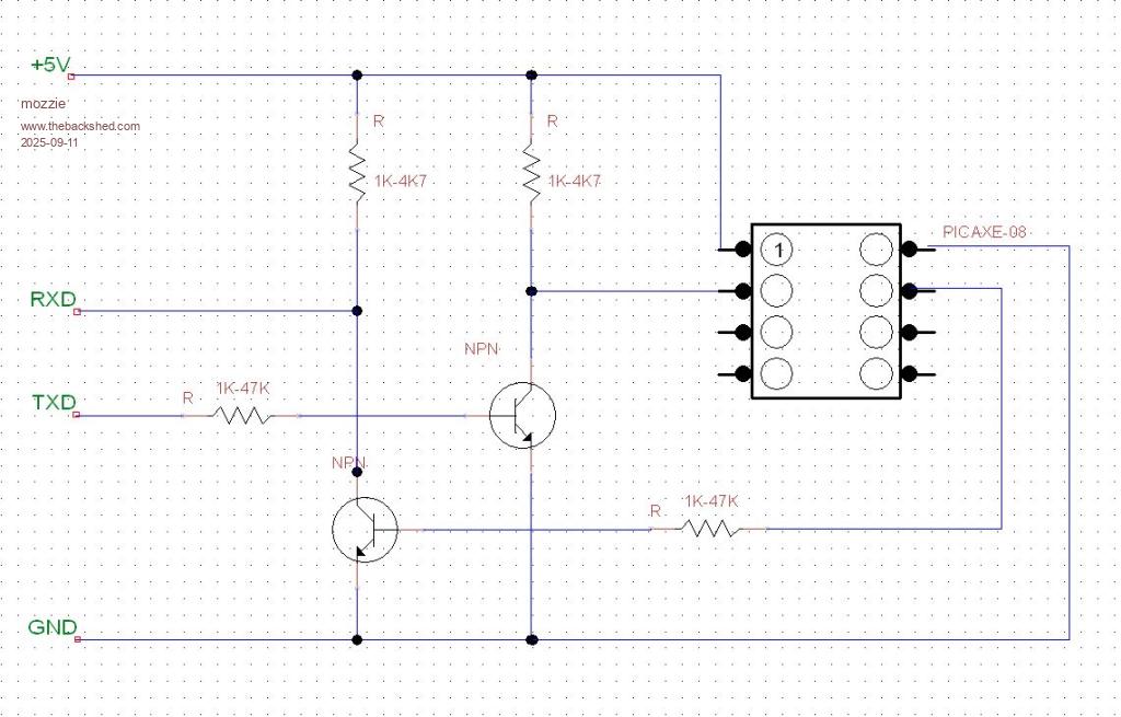
G'day Chris, Good news I hope I have tested the circuit desribed by Phil99 on a Picaxe08 and it works with a generic TTL232 lead
Hopefully you have a couple of generic NPN transistors and 4 resistors in a bitsa box somewhere, and you figured out which connection is which on your lead.
TXD = TX data from the converter cable, ditto for RXD = RX into the converter cable. Good Luck
Regards, Lyle.
Chrisk Senior Member Joined: 21/12/2014 Location: AustraliaPosts: 137
Posted: 01:34am 12 Sep 2025
Copy link to clipboard
Print this post
Hi All I tried putting inverters in the Rx and Tx lines and the message I got from the program wa that it couldn't find the device. I am taking a trip to visit Mossie so hopefully an answer will soon arrive.
phil99 Guru Joined: 11/02/2018 Location: AustraliaPosts: 3293
Posted: 01:51am 12 Sep 2025
Copy link to clipboard
Print this post
You can test the FTDI cable by unplugging it from the PICAXE and linking Tx (tip) to Rx (ring) then anything you type in TeraTerm should be echoed back to the screen, no matter what baud rate or signal polarity is used. . Edited 2025-09-12 11:56 by phil99
Chrisk Senior Member Joined: 21/12/2014 Location: AustraliaPosts: 137
Posted: 10:16am 15 Sep 2025
Copy link to clipboard
Print this post
Just in case this is required by someone in the future.
The solution was to invert the RxD and TxD lines as suggested by several members.
I used a 7400 quad NAND but it didn't seem to work, so postponed any further investigation as I had arranged a meeting with Mozzie.
Keep in mind that the 3.5mm audio connections are different to the actual AXE027 as mentioned by members. Where the Sleeve is GND, collar is RxD and the tip is TxD.
It's all working thanks to you guys and a BIG thank you to Mozzie who had this problem before and was able to carry out the procedure like a pro to fix my problem, using FT_Prog as mentioned by ElectroPI.
Thanks Mozzie and all the members who came in on the discussion.
And I thought the use of the PICAXE was going to be simple.
ElectroPI Regular Member Joined: 27/04/2012 Location: AustraliaPosts: 42
Posted: 04:36am 18 Sep 2025
Copy link to clipboard
Print this post
Great to hear you finally have the programming cable working.
It's worth mentioning that the FT232R is a great USB-to-serial interface IC. There are a few variations available from FTDI but I found the FT232R (28-pin SSOP package) is the most flexible and have built it into quite a few projects now, some using PICAXE but most using the 28-pin micromite.
What makes it so flexible is that FTDI's utility program FT_PROG allows you to change various parameters in its built-in EEPROM. So besides being able to invert the TxD and RxD signals you can also change the Manufacturer name, Product Description and Serial Number parameters among other things. For example you can set your name or company name as Manufacturer and the Product Description can describe your device exactly so it doesn't appear as a generic "Serial port" under "Ports (COM & LPT)" in Device Manager. This also applies to ready made USB-to-serial cables which use this IC (which is the subject of this thread).
Note that if designing a PCB to use the 28-pin SSOP IC or if soldering one in is a challenge then there's always a ready made module like Jaycar's XC4464. You can connect this to your PICAXE or micromite project and program its FT232R as required. All the best Peter
phil99 Guru Joined: 11/02/2018 Location: AustraliaPosts: 3293
Posted: 05:32am 18 Sep 2025
Copy link to clipboard
Print this post
$29 !! Not as flexible but much cheaper are CP2102, CH340 or PIC16F1455 programmed as a MicroBridge for TTL serial and ICSP for PIC32 chips.
ElectroPI Regular Member Joined: 27/04/2012 Location: AustraliaPosts: 42
Posted: 07:28am 18 Sep 2025
Copy link to clipboard
Print this post
Jaycar's part was just an example. There's lots of similar FT232R modules available on Ebay starting from below $5 & free postage. regards
Chrisk Senior Member Joined: 21/12/2014 Location: AustraliaPosts: 137
Posted: 02:04am 20 Sep 2025
Copy link to clipboard
Print this post
The fact that the driver comes up with what is a very generic name " Serial port" threw me a little because the thing wasn't working because Rx and Tx needed to inverted so I wasn't sure I even had the right driver installed.
Windows has previously told me in other projects that the correct driver is installed where in fact it wasn't.
I was going to play around and change from the generic name to something that would be something more specific, but due to the hassle just getting to this stage I thought I would best leave it alone.
Any tips on how to change the name would be appreciated.
Just another question. Why would you want to change Manufacturer name, Product Description and Serial Number parameters?
Thanks guys
phil99 Guru Joined: 11/02/2018 Location: AustraliaPosts: 3293
Posted: 05:22am 20 Sep 2025
Copy link to clipboard
Print this post
Those chips are probably used by manufacturers who want their name, product and its serial number to show up when it is plugged in.
You could set the name to "PICAXE Programmer" and the description to "Inverted TTL Serial"
I haven't used the software but the AN_124_User_Guide_For_FT_PROG.pdf describes it in section 5.4 USB_String_Descriptors.