
|
|
Forum Index : Microcontroller and PC projects : RP2040 program for Keypad with more than 4x4 keys.
| Author | Message | ||||
| phil99 Guru Joined: 11/02/2018 Location: AustraliaPosts: 3331 |
Yes, that should do it (after interpreting the typo **) though if I was going to add an IC perhaps Volhout's PCF8574 I2C solution would be the way to go as it has no need for calibration or any other components. It does however need an extra pin for an interrupt, but if I2C is already in use for an RTC etc. it is only adding 1 pin. ** Edit. Just seen your new post. I have been cramming the interrupt and reading the key on the same pin. Maintaining that and adding self calibration without adding too many components is proving tricky. Edited 2026-04-25 15:48 by phil99 |
||||
| robert.rozee Guru Joined: 31/12/2012 Location: New ZealandPosts: 2542 |
just realized that the LM334 can not pull the V+ pin to ground, it can only take it down to 1v. this may not be low enough for a logic LOW. but a second PNP transistor would solve the problem. cheers, rob :-) |
||||
| phil99 Guru Joined: 11/02/2018 Location: AustraliaPosts: 3331 |
Here is a slightly upgraded version of my analogue keypad. It still doesn't have as good a current source a Rob's (I don't have an LM334) but it is adequate for 4 x 4 keys. The main difference is it can drive a piezo speaker to beep with each keypress, without using an extra pin. A couple of extra capacitors are needed to offset the capacitance of the piezo speaker. It still doesn't have full self calibration but does fine-tune the settings each time the top left and bottom right keys are pressed. The updated values could be saved with VAR SAVE and restored on starting but if the initial calibration of the current source is good enough that isn't needed. Adjust the trim-pot for about 3 to 3.2V while the bottom right key is pressed then record that voltage and the voltage when the top left key is pressed. The latter should be less than 100mV. Edit the program setup to set those values. Eg. VcalL=0.02, VcalH=3.12 The circuit diagram was pinched from Rob's version and adapted. Hope you don't mind Rob. 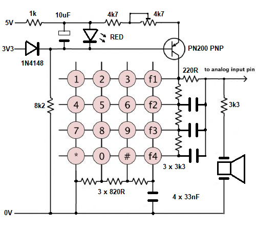 'Interrupt triggered analogue keypad driver with beeper using 1 pin. Dim Integer Rows=4, Cols=4, Key.pin=MM.Info(pinno GP28) Dim Float VcalL=0.02, VcalH=3.09 'calibration voltages - read while Lowest then Highest key pressed Dim map$(15)=("1","2","3","A","4","5","6","B","7","8","9","C","*","0","#","D") Dim Integer key1=-1, key2=-1, n SetPin Key.pin, intl, Key.int 'set key interrupt Print "Calibration values - VcalL =";VcalL; " VcalH ="; VcalH :Print Sub Key.int 'ISR SetPin Key.pin, ain Local key% = (Rows * Cols), KeyV, t If Pin(Key.pin) < 3.2 Then Pause 15 'de-bounce and capacitor charging time If Pin(Key.pin) < 3.2 Then KeyV = Pin(Key.pin) If KeyV >= 3.2 Or KeyV < 0.001 Then SetPin Key.pin, intl, Key.int 'restore interrupt Exit Sub EndIf Kcalc = (KeyV-VcalL) * 15 / (VcalH-VcalL) key1 = Cint(Kcalc) If Key1 = 0 And KeyV < VcalL+.4 Then VcalL = (VcalL + KeyV)/2 If Key1 = (Rows * Cols)-1 And KeyV > VcalH-0.4 And KeyV < VcalH+.4 Then VcalH = (VcalH + KeyV)/2 Print Format$(Cint(KeyV*1000),"% 5g"); " Key mV ", 'Comment out Print after adjusting pot for highest key voltage (2.9V to 3.1V) 'and setting the values of VcalL when top-left Key is pressed and VcalH when bottom-right Key is pressed EndIf t = Timer : Do While Pin(Key.pin) < 3.2 And Timer-t < 500 : Loop 'wait for key release SetPin Key.pin, Dout For n=0 To 400 : Key% = Not Key% : Pin(Key.pin) = Key% : Pause 0.2 : Next Print "Beep ", 'Comment out Print after calibration SetPin Key.pin, intl, Key.int 'restore interrupt End Sub Do 'main loop If key2 <> key1 And Key1 < Rows * Cols Then Print " Key no."; key1, "Key code "; map$(key1) Pause 150 'adjust repeat rate key1 = -1 : key2 = key1 EndIf Loop End > RUN Calibration values - VcalL = 0.02 VcalH = 3.09 17 Key mV Beep Key no. 0 Key code 1 305 Key mV Beep Key no. 1 Key code 2 434 Key mV Beep Key no. 2 Key code 3 643 Key mV Beep Key no. 3 Key code A 866 Key mV Beep Key no. 4 Key code 4 1150 Key mV Beep Key no. 6 Key code 6 1364 Key mV Beep Key no. 7 Key code B 1483 Key mV Beep Key no. 7 Key code B 1701 Key mV Beep Key no. 8 Key code 7 1907 Key mV Beep Key no. 9 Key code 8 2105 Key mV Beep Key no. 10 Key code 9 2330 Key mV Beep Key no. 11 Key code C 2542 Key mV Beep Key no. 12 Key code * 2762 Key mV Beep Key no. 13 Key code 0 2935 Key mV Beep Key no. 14 Key code # 3157 Key mV Beep Key no. 15 Key code D > Edited 2026-04-28 16:45 by phil99 Footnote added 2026-04-28 18:29 by phil99 Edit. There is a redundant variable in the Sub that can be removed. Replace Kcalc = (KeyV-VcalL) * 15 / (VcalH-VcalL) key1 = Cint(Kcalc) With key1 = Cint((KeyV-VcalL) * 15 / (VcalH-VcalL)) |
||||
| Volhout Guru Joined: 05/03/2018 Location: NetherlandsPosts: 6007 |
What a nice challenge.. the single pin keypad. 🙂 Volhout PicomiteVGA PETSCII ROBOTS |
||||
| ville56 Guru Joined: 08/06/2022 Location: AustriaPosts: 558 |
had a similar key-sensing mechanism in a Sony Cassette Deck about 40 years ago. They did it that way to be able to have a 3-wire remote control with more than 1 button and they also used that for the buttons on the front panel. IIRC there were 4 or 5 buttons only. 73 de OE1HGA, Gerald |
||||
| Mixtel90 Guru Joined: 05/10/2019 Location: United KingdomPosts: 8997 |
Surely the next step is to link two Pico Ws or a Pico W and a ESP for a no-pin keypad? :) Mick Zilog Inside! nascom.info for Nascom & Gemini Preliminary MMBasic docs & my PCB designs |
||||
| The Back Shed's forum code is written, and hosted, in Australia. | © JAQ Software 2026 |
