
|
|
Forum Index : Microcontroller and PC projects : All-in-one PIC18F46K22 dev. board
| Author | Message | ||||
| vasi Guru Joined: 23/03/2007 Location: RomaniaPosts: 1697 |
It is a home made 100x75 mm single-sided development board designed to put the PIC18F46K22 on a trial to see how it behaves compared to a Sanguino board. It is still on a "almost ready" state but can be used as it is. I chose to have it instead of a "Sanguino breadboard" style board which, together with a big breadboard would have occupied a lot of space on my small office. 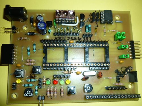
It is still missing a 7805 regulator (it powers from USB-to-Serial adapter), a 5v1 Zener diode protection for a resistive divider (measuring up to +55Vcc but is ok if I don't get close to the maximum voltage) and those two trimpots are just for show (not soldered) as they are 100K instead of 10K - one is for testing the ADC, the other is for LCD contrast. 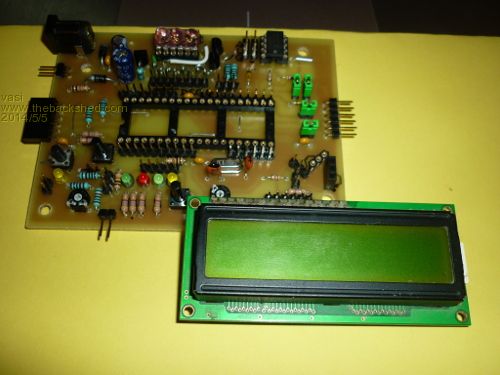
It has a PCF8583 as RTC (not tested yet) with two jumpers for 4k7 pull-up resistors and a smd battery socket bellow the board, a serial connection (Arduino standard) with a jumper on VCC and the another on the automatic reset function (which is not used by the actual bootloader, a modified AN1310 serial bootloader who needs a button to enter in boot mode): 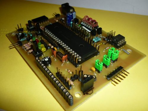
The taller 3pin female connector (Arduino socket style) is to accommodate an interchangeable IR decoder (for 36, 38 or 40 KHz) and the smaller 3pin female connector is for a Dallas temperature sensor. The longer female connector is for 16x2 LCD display: 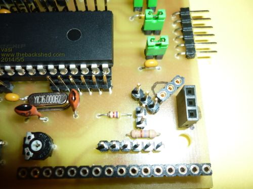
There are 2 user buttons, 4 user LEDs, a trimpot for ADC testing, a resistive divider for measuring external voltages, an ICSP connector (the black horizontal 6pin female connector): 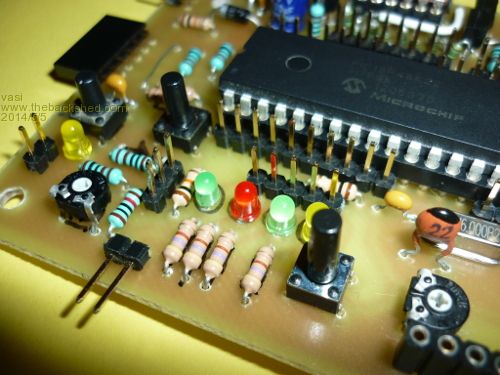
12 years ago I recovered from a vintage computer board this Bubble Display (3 digits 7 segment) which I had no immediate use for it (not even curious to see the pinout), with the code "HP 5082 7433" It was hard to fit into such a small space and a single-sided design but now is ready to be stressed (datasheet here - and here, you can find a 4 digits one on ebay): 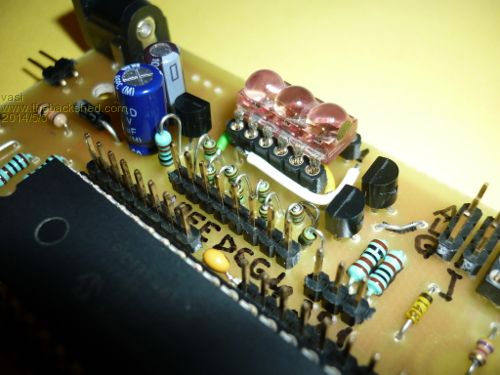
Until now, I've tested only the bootloader and did a blink a LED test. Personally, I'm not happy with the final result. Originally, the board was 100x80 mm (the maximum on Eagle Lite) then I had to resize it to 100x75 mm because it was what I had available, then I had to move the peripherals around to make space for the Bubble Display which was a last minute addition (remembered that I had it and I thought it would make a better impression than a single, regular 7seg. digit). All the other male connectors are for connecting the micro pins with the peripherals and also there are two buses (I2C and 1wire). Vasi Hobbit name: Togo Toadfoot of Frogmorton Elvish name: Mablung Miriel Beyound Arduino Lang |
||||
| vasi Guru Joined: 23/03/2007 Location: RomaniaPosts: 1697 |
These are the sources of the serial bootloader - it needs only MPLAB-X to be compiled and then, a connection between one of the two user buttons and RA4 pin for entering in boot mode, and a connection between one of the four user LEDs and RC2 pin for boot mode indicator. 2014-05-05_145227_PIC18F46K22_EVB_RA4_64MHz_19200.zip Regarding the schematic board, te advantage of this approach, is that there is ... no schematic. There are only separate modules, and you really are starting to create a schematic when you start routing the modules with connection wires for a specific application or example, and then, you can provide a schematic. Hobbit name: Togo Toadfoot of Frogmorton Elvish name: Mablung Miriel Beyound Arduino Lang |
||||
| vasi Guru Joined: 23/03/2007 Location: RomaniaPosts: 1697 |
Anyway, this is the initial Eagle project, before starting to fit the Bubble Display. I will start from this project again in the future, to redo the board, trying to make it much prettier and maybe adding some more peripherals... But not so soon. 2014-05-05_151517_pic18f46k22_evb.zip Hobbit name: Togo Toadfoot of Frogmorton Elvish name: Mablung Miriel Beyound Arduino Lang |
||||
| atmega8 Guru Joined: 19/11/2013 Location: GermanyPosts: 738 |
Very nice, Vasi... THX |
||||
| vasi Guru Joined: 23/03/2007 Location: RomaniaPosts: 1697 |
Take care about the 40pin footprint, it was converted with a Microchip tool for Eagle, as Eagle don't have that micro, and I had to bend the pins of a 40pin socket to force it to enter in the holes. You can replace it without problems with a PIC18F4550 footprint, as there are perfect matches for pinout. I insist in continuing with Eagle as from here it can be exported to both KiCAD and DipTrace eda packages. I would have used KiCAD because I'm working in Linux but then not much use for many. Now, where to get the Eagle components: - ds1307 - pcf8583 RTC; - DS1820 - temperature sensor; - TSOP48xx - IR Receiver; As for RS485, you have an equivalent in LTC485N from Linear Technology, included already in Eagle 6.x. Not sure if the same pinout. A DS18B20 TO92 component can be found here, where you can get many more useful libraries. Hobbit name: Togo Toadfoot of Frogmorton Elvish name: Mablung Miriel Beyound Arduino Lang |
||||
| vasi Guru Joined: 23/03/2007 Location: RomaniaPosts: 1697 |
When I inserted the 40pin socket in the PCB holes, it got like this one: 
I don't know if is the fault of the conversion tool recommended by Microchip, or it is an old problem of Eagle printing in Linux... but I changed that socket with a "Eagle native" one. 2014-05-06_162404_pic18f46k22_evb.zip Hobbit name: Togo Toadfoot of Frogmorton Elvish name: Mablung Miriel Beyound Arduino Lang |
||||
| vasi Guru Joined: 23/03/2007 Location: RomaniaPosts: 1697 |
Here is the first test of the Bubble Display . I intend to make a web page on my site to present there all the libraries, examples, projects and schematics, as I have some kind of version control for files. As for PCF8583, just successfully tested two types of alarms (daily alarms and weekdays alarms where you chose on which days of the week your alarm is active). Hobbit name: Togo Toadfoot of Frogmorton Elvish name: Mablung Miriel Beyound Arduino Lang |
||||
| vasi Guru Joined: 23/03/2007 Location: RomaniaPosts: 1697 |
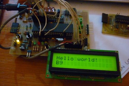
Pretty messy, but it works. It is a JAL LCD example which come with the standard Jallib package. 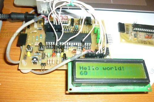
Hobbit name: Togo Toadfoot of Frogmorton Elvish name: Mablung Miriel Beyound Arduino Lang |
||||
| vasi Guru Joined: 23/03/2007 Location: RomaniaPosts: 1697 |
The four digit bubble displays may be found at Sparkfun. 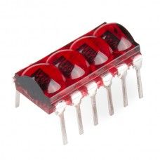
And my board may look like this at some point in the future... 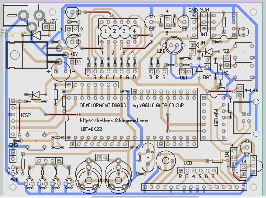
And it may include: - 1x4digit bubble display, - 1 2x16 LCD - 1 RGB LED - 1 PCF8583 (external battery) - 1 I2C bus - 1 1wire bus - 1 DS18B20 - 1 IR receiver (36,38,40KHz) - 4 LEDs - 2 user buttons - 2 10K pots - 1 resistive divider for real life voltage measurement - 1 USB_to_Serial with PIC16F1454 But until then, I'm using my actual board, and some of the C code is available on googlecode.com. Actually, on github now. Hobbit name: Togo Toadfoot of Frogmorton Elvish name: Mablung Miriel Beyound Arduino Lang |
||||
| The Back Shed's forum code is written, and hosted, in Australia. | © JAQ Software 2026 |
