
|
|
Forum Index : Microcontroller and PC projects : [MicroMite]AD9850 Controller Source Code
| Author | Message | ||||
| paceman Guru Joined: 07/10/2011 Location: AustraliaPosts: 1329 |
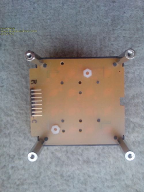
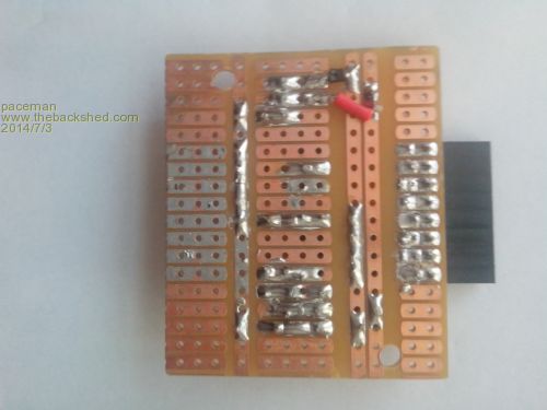
Thanks Peter, actually SMD on stripboard (or proto board) works pretty well. That controller has an 0805 10K resistor, two 1206 capacitors and the SOT23 3.3v reg on it. The spaces between the "strips" isolates each end of them nicely, and cutting a 1mm break in a strip for them also works well. The reg slotted in nicely with a separate strip for each of the three 'pins' and the live 3.3v base on the 'rail' strip - you can see it in the photo. My program to drive it is here UV Box Timer . The final post gives the code with the PWM brightness control added. This link 4x4 Methods has a discussion on methods for using analogue input for a keypad. And this link 4x4 Keypad is good documentation for the original work. Since doing the board for that I've changed the ribbon cable connector method shown in the photo to a much simpler right angle pin method as in the photos below. This method is great as it's quick to do and allows you to quickly swap the board in and out to change between the analogue and parallel methods for proto-ing. It's also a solid permanent connector. There are several other threads - search the forum with "4x4" or "4 x 4" or "keypad" etc. Greg 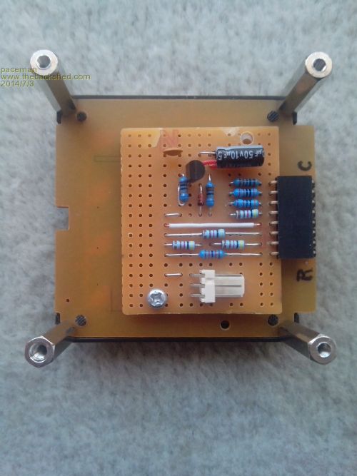
|
||||
| Keith W. Senior Member Joined: 09/10/2011 Location: AustraliaPosts: 118 |
Peter, Thank you for publishing your code. For a DDS generator I have used a 2 line * 16 character LCD display. No, not yet using MMBasic though your code will help greatly. Four individual pushbuttons enable save and recall of frequencies, mode change etc. Holding down one button converts the dial to move the display cursor below the frequency display digits to select the required adjustment decade. Higher or lower, depending upon the dial direction and thereby indicating the decade. The dial operation reverts to adjusting the frequency upon releasing the button. Most LCD’s allow cursor positioning; I call a cursor location sub after each display of frequency. This has proved a convenient technique and I do not miss a keypad. In my applications normally the frequency will be set and then adjusted at a set increment, i.e. at 1 KHz if for SDR coarse tuning. Keith W. |
||||
| G8JCF Guru Joined: 15/05/2014 Location: United KingdomPosts: 676 |
Hi Keith Your scheme seems quite useful indeed, well worth bearing in mind for a VFO for a rig. I'm intending to create an antenna analyser/component analyser/sweep generator/vfo for the HF amateur, and I'd like to try and make the user interface/ergonomics as straightforward as possible hence why I think a keypad might be the best way to go. Of course it could all change as I build up the system ! Once again, thank you for sharing your ideas. 73 Peter The only Konstant is Change |
||||
| Keith W. Senior Member Joined: 09/10/2011 Location: AustraliaPosts: 118 |
Hi Peter, My AD9954 DDS Source is also controllable via RS232 from a PC. Find enclosed a view of my sweep application when plotting the response of a simple band pass filter, a fair match to the “Elsie” filter design. 2014-07-04_121648_Filter_response.zip The DDS controlling MC68HC912b32 micro also runs an I2C connected power detector head that uses an AD8307 log detector chip, an amplifier and an 8 pin PIC for I2C comms and analog to digital. The GUI is programmed in Delphi. Obsolete, but it still works under Windows 7. I can sweep my G5RV antenna via an impedance bridge which indicates that is about correct dimensions and matches at Ham HF frequencies. I am not a Ham and listen only, but my father was from 1920’s. My career did not require much hands on RF as others specialized but have been playing in retirement. I seem to enjoy designing and building test equipment. Became interested in and have built an SDR similar to designs by YU1LM. Keith W. |
||||
| The Back Shed's forum code is written, and hosted, in Australia. | © JAQ Software 2026 |
