Notice. New forum software under development. It's going to miss a few functions and look a bit ugly for a while, but I'm working on it full time now as the old forum was too unstable. Couple days, all good. If you notice any issues, please contact me.
plasma Guru Joined: 08/04/2012 Location: GermanyPosts: 437
Posted: 11:32am 27 Jul 2014
Copy link to clipboard
Print this post
Hi,
anyone knows a cool method for switching data lines ( rx/tx/) to use two serial modules on one com port ?
thx
JohnS Guru Joined: 18/11/2011 Location: United KingdomPosts: 4335
Posted: 11:55am 27 Jul 2014
Copy link to clipboard
Print this post
CD4066 maybe?
John
G8JCF Guru Joined: 15/05/2014 Location: United KingdomPosts: 676
Posted: 01:45pm 27 Jul 2014
Copy link to clipboard
Print this post
@plasma
True RS232 serial or TTL serial ?
Not cool, but simple, a Double Pole Change Over toggle switch :)
PeterEdited by G8JCF 2014-07-28The only Konstant is Change
Grogster Admin Group Joined: 31/12/2012 Location: New ZealandPosts: 9975
Posted: 03:05pm 27 Jul 2014
Copy link to clipboard
Print this post
I still think switches are pretty cool.
This is exactly how I did it on one product - a "RUN" and "PROGRAM" switch, on the back panel, or jumpers on the PCB.
HOWEVER, that is for programming. If you wanted to be able to use two devices on the same port at the same time, that's a bit more tricky. I seem to recall on the PICAXE forums, that you could use simple diode-mixing to a common serial line - kind of like a serial version of I2C, where you have several serial devices on one serial port, and they are programmed to respond to certain commands, and ignore others for other modules kind of thing. Might not work in you situation, but just chucking the idea out there.... Smoke makes things work. When the smoke gets out, it stops!
G8JCF Guru Joined: 15/05/2014 Location: United KingdomPosts: 676
Posted: 03:12pm 27 Jul 2014
Copy link to clipboard
Print this post
@plasma
The key drivers are
a) Software controlled or manually controlled ?
b) Real RS232 or TTL/3V3 Serial
PeterThe only Konstant is Change
Lou Senior Member Joined: 01/02/2014 Location: United StatesPosts: 229
Posted: 04:19pm 27 Jul 2014
Copy link to clipboard
Print this post
plasma,
Maybe not that cool but how about multi-drop RS485/422 ??
One more chip + addressing the module you want to talk to.
LouMicrocontrollers - the other white meat
WhiteWizzard Guru Joined: 05/04/2013 Location: United KingdomPosts: 2991
Posted: 10:36pm 27 Jul 2014
Copy link to clipboard
Print this post
@plasma,
As stated elsewhere, I am successfully using a 4066 to switch between two COM devices to a MicroMite.
I use two MicroMite I/Os to control the 4066's; one I/O goes to two of the four switches in the 4066 and switches the Rx and Tx from the device 1 to the MicroMite; and the other I/O goes to the other two switches in the 4066 to connect device 2 to the MicroMite. This gives me the ability to disconnect both devices, as well as connecting either device to the MicroMite.
I purposely did not use one I/O and an invertor as I need a delay of 100mS between switching (i.e. needed both to be disconnected for this duration).
The above assumes TTL levels; however I have used a self-latching DPDT relay for 12v switching between two RS232 devices (between two RFID readers and a control box).
WW
plasma Guru Joined: 08/04/2012 Location: GermanyPosts: 437
Posted: 05:27am 28 Jul 2014
Copy link to clipboard
Print this post
ok i go with the 4066 . thx again
Grogster Admin Group Joined: 31/12/2012 Location: New ZealandPosts: 9975
Posted: 02:20pm 04 Aug 2014
Copy link to clipboard
Print this post
@ WW: I have a need for something similar myself now, and rather then use a mechanical switch or relay, I like the CMOS idea. Could you please post your schematic of how you wired the 4066 into the MM, so I can get an idea of how to plagiarize your idea? Smoke makes things work. When the smoke gets out, it stops!
WhiteWizzard Guru Joined: 05/04/2013 Location: United KingdomPosts: 2991
Posted: 03:30am 05 Aug 2014
Copy link to clipboard
Print this post
@Grogs
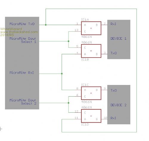
Hope this gives the general idea . . .
If you are not familiar with the 4066, it is basically four SPST switches in a 14pin package. Each switch has a control signal 'C' that opens or closes the switch depending on logic level applied to 'C'. The switch is between 'A' and 'B'. There is no specific input or output to a switch so A and B connections can be interchanged to make any PCB layout easier.
The above circuit uses two MicroMite I/O pins (set to Dout) to select either Device 1 or Device 2 to be connected to the MicroMite COM port. Ensure your software does NOT select both Devices simultaneously otherwise potential damage may occur to your Devices.
Alternatively (if you only have one spare MicroMite I/O pin) use just the one I/O pin connected to one half of the 4066 (i.e. pins 13 & 5) with an invertor to the other half of the 4066 (pins 6 & 12).
Let me know if you need more info . . . .
WW
Grogster Admin Group Joined: 31/12/2012 Location: New ZealandPosts: 9975
Posted: 01:29pm 05 Aug 2014
Copy link to clipboard
Print this post
Lovely, thanks buddy.
I downloaded a PDF for a 4066, but was trying to work out how the switches worked.
This was the paragraph that lit the light-bulb in my head - thanks. I have not used 4066's before, so it was a new chip to me.
Many thanks. Smoke makes things work. When the smoke gets out, it stops!