
|
|
Forum Index : Microcontroller and PC projects : Voltage to PWM for PC Fans
| Author | Message | ||||
jman Guru Joined: 12/06/2011 Location: New ZealandPosts: 711 |
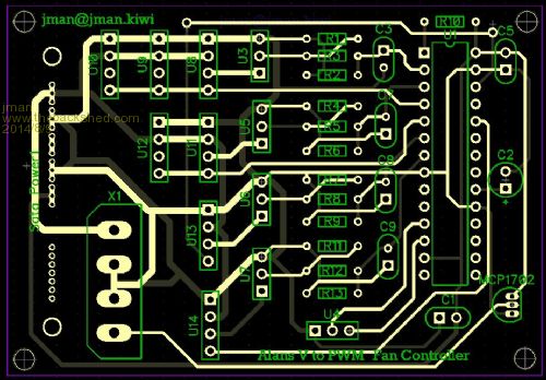
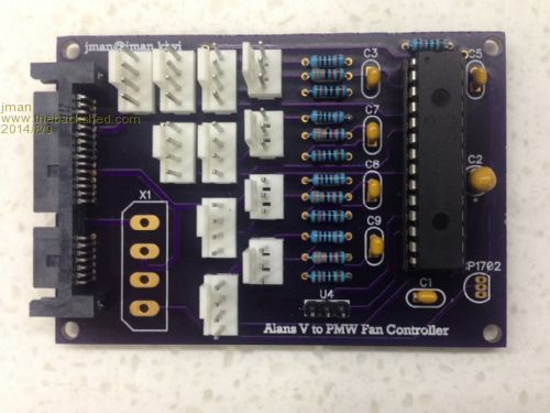
Hi My Son got a new Motherboard for his PC and decided to add a new case and water cooling while he was at it. This lead to him purchasing some new high quality fans. the fans he purchased were 4 wire fans (PWM controlled) but the new motherboard controlled the fans via voltage not PWM (Except for the PCU Fan) so time to breakout the Micromite and make a Voltage to PWM converter. This what I came up with it is installed in the new PC and working like a charm I used a SATA connector for the power as this has a 3.3v to power the Micromite. The basic program is attached. The PCB will fit into a 3.5' hard disk bay so it can be mounted easily. 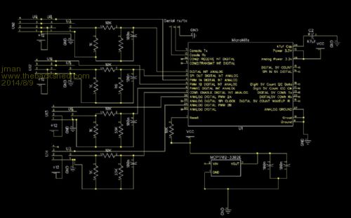
Excuse the stupid type O (PMW) 2014-08-09_081049_FanCtr.zip Regards Jman |
||||
| WhiteWizzard Guru Joined: 05/04/2013 Location: United KingdomPosts: 2991 |
Another brilliant use for the MicroMite 
I have had a quick look at your circuit (in zip file) and also at the photo above. I understand everything in your photo on the right hand side from the two sets of 4 white connectors. However, can you quickly clarify a few things: I assume the SATA connector is the black connector on the left hand side? What is X1 for? Are the three white connectors (1+2) above X1 for the voltage inputs? If so then why not four? Sorry if these seem like silly questions; especially as you have been working on this for a little while. Like I say, I just glanced at it and have a use for something similar and hence the real interest. Thanks for posting your project . . . . . WW |
||||
| jman Guru Joined: 12/06/2011 Location: New ZealandPosts: 711 |
@WW X1 is there if you want to use a normal Molex hard drive power connector you will also need to fit the 3.3v Regulator Yip the SATA connector is the black bit on the left (Through hole version) The voltage inputs are the 4x 3pin connectors the outputs are the 7x 4pin connectors Channel 1 has 3 outputs Channel 2 has 2 outputs Channel 3 and 4 have 1 output each The 4pin connector closet to the 3pin connector also supply's the tacho pulse Regards Jman |
||||
BobD Guru Joined: 07/12/2011 Location: AustraliaPosts: 935 |
John what brand and model was the mother board that your son used? have you considered putting a usb connection to the board and permanently wiring it back to the PC to allow setting the fan speeds via Tera Term or other? edit: delete the second question. Bob |
||||
| jman Guru Joined: 12/06/2011 Location: New ZealandPosts: 711 |
@Bob The motherboard is an Asus Maximus VII Hero It came with a real nice GUI application that controls the fans so he using that to talk to the Maximite etc.. Screenshot below 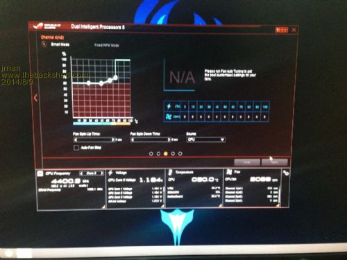
Regards Jman |
||||
kiiid Guru Joined: 11/05/2013 Location: United KingdomPosts: 671 |
Datasheet http://rittle.org -------------- |
||||
| paceman Guru Joined: 07/10/2011 Location: AustraliaPosts: 1329 |
Nice looking board John - we'll forgive the PMW instead of PWM 
Greg |
||||
| viscomjim Guru Joined: 08/01/2014 Location: United StatesPosts: 925 |
Hi Jman, Took a quick look at the zip file and program. Very cool! What program do you use to do your pc boards? Also in line 13 (not including blank lines) of your code it says PWM 2, 25000, 10, 10 should that be PWM 1,25000,10,10? or am I not getting it? Again, nice unit! |
||||
| jman Guru Joined: 12/06/2011 Location: New ZealandPosts: 711 |
@ Viscomjim Well spotted "You are getting it perfectly" It should read "PWM 1, 25000, 10, 10 " That brings the fans down to dead slow after the initial spin up I use DipTrace for my PCB's Thanks for comments Regards Jman |
||||
jebz Regular Member Joined: 13/06/2011 Location: AustraliaPosts: 79 |
Geoff has a good fan controller project at - http://geoffg.net/fancontroller.html Both projects have some nice features. |
||||
| The Back Shed's forum code is written, and hosted, in Australia. | © JAQ Software 2026 |
