
|
|
Forum Index : Microcontroller and PC projects : pic32mx170f256b QFN package
| Author | Message | ||||
| viscomjim Guru Joined: 08/01/2014 Location: United StatesPosts: 925 |
Hi all, I am trying to implement a GSM module that has the 28 pin pic32mx170f256b chip but in a QFN package instead of the 28 pin dip. It is loaded with MMbasic 4.5c. Obviously the pin numbers are different between the two packages. Is there any reason why, if I map the pins from the QFN package to the DIP pacakge pins that mmbasic uses for the 28 pin, that this chip would not work properly with MMbasic? Is there any difference between the two other than the pin numbers being off? Thanks!!!! |
||||
| Geoffg Guru Joined: 06/06/2011 Location: AustraliaPosts: 3362 |
You should be Ok. Have you checked the 44-pin firmware as that could be closer to the number of pins on the QFN package? Geoff Geoff Graham - http://geoffg.net |
||||
| viscomjim Guru Joined: 08/01/2014 Location: United StatesPosts: 925 |
Hi Geoff, the pic32mx170f256b in the QFN and the DIP are both 28 pins. The QFN part is part of a pcb module with a gsm modem on it in an xbee footprint. The pic32 pins are just not labeled the same per pin number. I have gotten the console to work using pins 8 and 9 on the QFN part (normally 11 and 12 on the DIP part). I tried to hook up an I2C lcd display using pin 14 for I2C CLK and 15 for I2C Data (pins 17 and 18 respectively on the 28 DIP), it did not work. So to try and narrow it down, I just stuck an LED on both pins (14 and 15 on the QFN part), ran the following... SETPIN 17, DOUT SETPIN 18, DOUT DO PIN(17)=0 PIN(18)=1 PAUSE 200 PIN(17)=1 PIN(18)=0 PAUSE 200 LOOP I get this... > RUN [1] SetPin 17, DOUT Error: Invalid pin Same error for pin 18 also. I followed the pin number and function on the pic32 data sheet to remap the physical pins of the QFN to the MMbasic pin names for the 28 pin DIP. Am I not doing this correctly? Thanks again for an awesome product and your great efforts!!! |
||||
| Geoffg Guru Joined: 06/06/2011 Location: AustraliaPosts: 3362 |
Sorry, yes the QFN package runs the same firmware as the 28 pin DIP. But I am worried by this error that you are getting. Pin 17 is a valid pin, SETPIN on it should work. It does not matter if you have mapped the pin numbers incorrectly, that command should still work. I have gone through the source and I cannot see how that error could be generated but I don't have a chip to test it on. Could someone with a 28-pin MX170 (Peter? Rob?) please try and run the following command at the command prompt: SETPIN 17, DOUT
and report the result (you should get nothing and especially not an error message). Geoff Geoff Graham - http://geoffg.net |
||||
| G8JCF Guru Joined: 15/05/2014 Location: United KingdomPosts: 676 |
Hi Geoff I've just done 'setpin d17, dout' on a 170F 28 pin (sdip) and nothing is reported back, ie behaves as expected Peter The only Konstant is Change |
||||
| viscomjim Guru Joined: 08/01/2014 Location: United StatesPosts: 925 |
Just in case, pin 17 on the QFN package is Vcap and pin 17 on 28 pin dip is I2C clk and regular IO pin (the one I want to use). Also, I am running 4.5C not D as I can't program it right now (But I don't think that matters). Still can't figure it out. I am pretty certain that MMbasic for 28 pin dip doesn't know I am running on a QFN package. The pin definitions on the data sheet show what pin numbers are used and I am simply "mapping" them by name to MMbasic for 28 pin dip (sounds confusing). |
||||
| Geoffg Guru Joined: 06/06/2011 Location: AustraliaPosts: 3362 |
Thanks Peter, I can relax now. @viscomjim, you are right - MMBasic would not know what package it is running on so when you refer to pin 17 in MMBasic the physical pin on the QFN package would be 14. Regardless, you should not get an "Invalid pin" error. Running 4.5C might be a clue but I cannot think how. Whatever is going wrong seems to be happening to you only so you will need to do some experimenting. Test SETPIN 17, DOUT at the console, check the actual chip part number, load the 4.5D 28-pin MX170 firmware, etc, etc. Geoff Geoff Graham - http://geoffg.net |
||||
| viscomjim Guru Joined: 08/01/2014 Location: United StatesPosts: 925 |
I will give the 170 code a whirl and see what happens. Thanks for your help!!! |
||||
| viscomjim Guru Joined: 08/01/2014 Location: United StatesPosts: 925 |
Quick update... Loaded MMBasic 4.5D for 28 pin 170 and ALL IS WELL!!! Not sure what in the world was going on earlier with this. Now that I can work with the uMite on this board, its time to get the gsm working. This is a pretty amazing board the size of an xbee with a pic32 170 on it. Here is a pic of the board with antenna and an i2c 20x4 LCD hooked up to it. Very small unit... 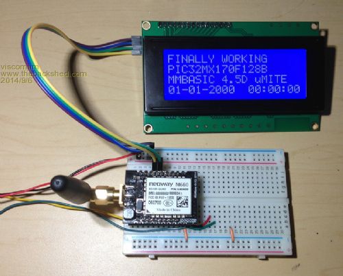
|
||||
| Geoffg Guru Joined: 06/06/2011 Location: AustraliaPosts: 3362 |
That looks like an interesting module. Can you give us any details? Part number? Supplier? Price? Geoff Geoff Graham - http://geoffg.net |
||||
| viscomjim Guru Joined: 08/01/2014 Location: United StatesPosts: 925 |
The board is the one described in this thread It is a cellular modem which you can see on the top of the board and the pic32 is on the bottom in the small qfn package. I purchased this board from Kon at Dimitech and I believe I paid $40.00. The board was well thought out as far as the xbee footprint having the weird pin spacing, Kon put .1 pin spacing on the two sides of the board so it could plug into a breadboard. Unfortunately, I did not ask for that and mine came in with xbee pins installed. I purchased an xbee breakout board from parallax and used that to plug into my breadboard. I have yet to work with the GSM part, but will do that shortly and report back. The antenna is off one of my other gsm modem boards of which I will also be using the sim card to test this unit. |
||||
| The Back Shed's forum code is written, and hosted, in Australia. | © JAQ Software 2026 |
