
|
|
Forum Index : Microcontroller and PC projects : 8, 14 & 18 pin DIL versions of 170 uM...
| Author | Message | ||||
bigmik Guru Joined: 20/06/2011 Location: AustraliaPosts: 2981 |
TZ, I hear what you are saying and in general it is good advice.. I can increase pad a little to increase grip to the pcb substrate.. I don't think I can squeeze vias in the pads though.. I can look at it though..it is only 8 pins to force into an IC socket which if it is intended to be removed over and over the IC socket can be replaced with female single header pins so insertion/removal force will be minimised.. Phil, I always intend to add copper pours both sides.. I didn't include them for clarity.. There is also a bug in the latest DEX with copper pours with thermal relief where the vias connected to gnd get isolated and lose their connection to gnd ... I can pour with no thermal relief... Probably still OK on this board. All, I have heard back from sitopway. Due to the small size they have to panel as 5x5 vee grooved and 6 pieces would be $65us about $75aus for 150 boards which is fine but could I move 150? Also they accept down to 0.006"/0.15mm tracks/clearances this gets close, I am sure I am over that... Just... That included DHL shipping too. Anyway food for thought. Mick Mick's uMite Stuff can be found >>> HERE (Kindly hosted by Dontronics) <<< |
||||
| robert.rozee Guru Joined: 31/12/2012 Location: New ZealandPosts: 2529 |
a little off topic, but a 28-pin DIP version would not be entirely silly, if it added value by connecting together all the Vcc and ground pins, and had the core filter capacitor and reset pullup resistor onboard. this would provide a simpler hookup when using a solderless breadboard. here is a small carrier board i've made out of veroboard. it has proven to be surprisingly useful: 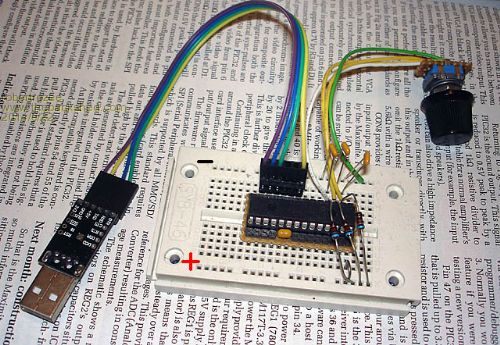
underneath, pins 8, 19, and 27 are linked (gnd). pins 13 and 28 are linked (Vcc). there is a 10k resistor between pins 1 and 28. there is (visible in photo) a 10uF ceramic capacitor between pins 19 and 20 (header pins 19 and 20 are removed) i should have replaced header pins 8, 11, 12, and 13 with 20mm long pins, creating an on-board serial/power header. the assembly is 0.5" wide between header rows. using an SMD 32MX, there would be space on the PCB to add a reset button. when plugged into a solderless breadboard, one just has to jumper pin 28 to the Vcc strip, and pin 8 to ground strip. rob :-) |
||||
Grogster Admin Group Joined: 31/12/2012 Location: New ZealandPosts: 9975 |
How about this for a mad idea around that problem: As all the components are on the top layer, and the bottom layer is just tracks/vias and the pads for the SMD connectors, once the module is assembled, carefully smear a layer of(reasonably thick) epoxy glue over the bottom of the board to protect and strengthen it. Once set, this stuff is rock-hard, and would greatly strengthen the underside pins against them pulling the pads off the board. Sort of how they put that "Blob" of resin over LCD controller chips which are bonded to the PCB, to protect them. Smoke makes things work. When the smoke gets out, it stops! |
||||
| bigmik Guru Joined: 20/06/2011 Location: AustraliaPosts: 2981 |
Grogs, That sounds like a perfect work around to the problem.. I did look on fee-bay for single SMD pins and they are rare on there.. So I bought dual row type and will have to manually, make singles by transferring the pins to a sacrificial straight row strip. Not too hard for 8 pins, but I wouldn't want to do a lot.. The singles are available on e14 etcetera but they aren't cheap. Mick Mick's uMite Stuff can be found >>> HERE (Kindly hosted by Dontronics) <<< |
||||
| vegipete Guru Joined: 29/01/2013 Location: CanadaPosts: 1180 |
If you use the SSOP instead of the QFN, you can push the chip off to the side so that through hole headers can be used. Solder the pins in first, ensuring that they don't stick through the board, then solder the chip itself on. There's room underneath for a few 0805s, and the ICSP (USB/Serial) header is off to the side with 0.050" pitch. As drawn, the PCB is about 0.5 x 0.525 inches. 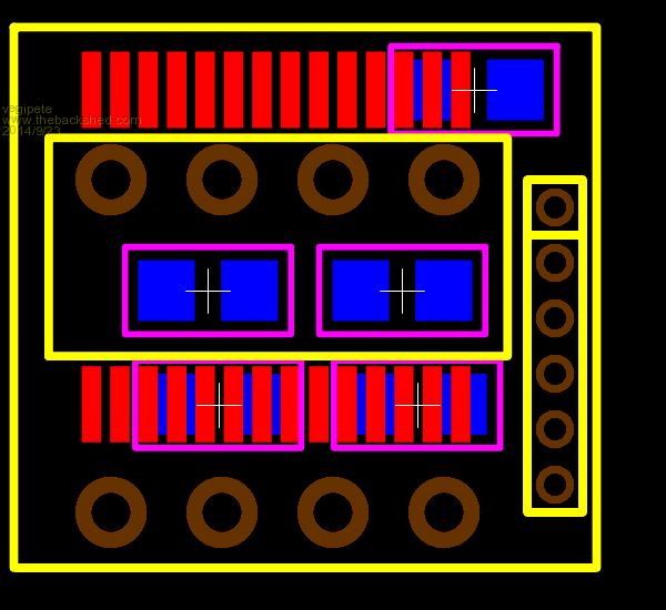
Visit Vegipete's *Mite Library for cool programs. |
||||
| bigmik Guru Joined: 20/06/2011 Location: AustraliaPosts: 2981 |
Hi Vegipete, I did think of that option but to do `configurable' pins would mean a larger board than my 15mm square one.. It is certainly an answer if only 1 option is provided for OR you lose the ICSP header and put config pads along that edge. Regards, Mick Mick's uMite Stuff can be found >>> HERE (Kindly hosted by Dontronics) <<< |
||||
| bigmik Guru Joined: 20/06/2011 Location: AustraliaPosts: 2981 |
Hi Lads, It LIVES Here is a prototype I have Dubbed MuP-Mini. 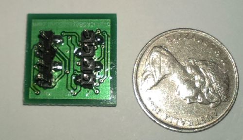
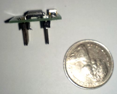
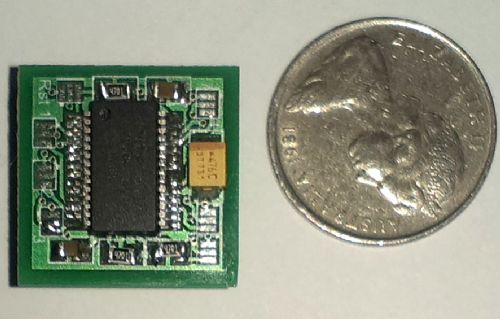
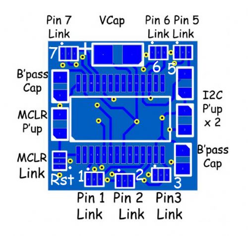
Soldering the 0805 Resistors and Caps were a `right pain' but it seems to work quite well. That is an Australian 5c coin for size comparisons in the photos. As has been happening quite a bit lately, there is an error in my layout that means that MCLR and PCC cannot be configured at the same time and are mutally exclusive, meaning that to flash the chip with MMBasic require a flying lead from the PicKit to MCLR on the PCB.. Once flashed the configurations of the pins sem to work as expected. I will be doing a new one and this version will not be released as a product, I will also look at the pin configurations as I currently have 2 of the SPI pins but not the third and I want to add COM1 to it as well. But look at the table attached here (ignore the MCLR line a it doesnt work as mentioned) 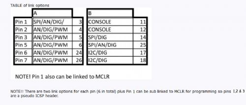
I panelised these boards on a 10cm x 10cm panel and got a cheap prototype done and figuring that I would need to cut them using a bandsaw I separated them by 2mm to allow for the cut.. They Vee-grooved them for me so these boards are actually 17mm x 17mm in size instead of 15mm x 15mm (you can see the extra boundary in the photos) If anyone is interested in a block of 9 (3 x 3) PM me and I am happy to ship them as freebies just cover postage and paypal fees. Lets say $2 for AUSTRALIA and $4 rest of the world. I have about 30 panels of 9 I can offer.. If someone is really enthusiastic I am happy to supply more but I figured as a trial 9 is plenty. The new boards, hopefully, will be available in about a month. Regards, Mick Mick's uMite Stuff can be found >>> HERE (Kindly hosted by Dontronics) <<< |
||||
| The Back Shed's forum code is written, and hosted, in Australia. | © JAQ Software 2026 |
