
|
|
Forum Index : Microcontroller and PC projects : Maximite Video issues
| Author | Message | ||||
| oddsoul Newbie Joined: 05/11/2014 Location: AustraliaPosts: 5 |
Hello everyone! Having an issue with a recently built Maximite Colour. The video that is displayed is very dull and doesn't seem to have much brightness to it. Have I done something wrong? or is there something that needs to be done to rectify this? |
||||
TassyJim Guru Joined: 07/08/2011 Location: AustraliaPosts: 6538 |
Welcome to the forum. There are only two things which can affect the brightness of the VGA output. The 3 diodes which are forward biased and set the level to approximately 0.6 volts. If these are the wrong type the forward voltage could be 0.2 volts. If they are in backwards, the voltage would be too high so it's not that. The other problem could be the 3 120 ohm resistors from the CPU to the diodes. If these are the wrong value and too high, the output would be limited also. There isn't really anything else... Can you check the outputs, preferably with a CRO? Alternatively, program it so you have a white screen and measure the three outputs with a multimeter. Jim VK7JH MMedit |
||||
| oddsoul Newbie Joined: 05/11/2014 Location: AustraliaPosts: 5 |
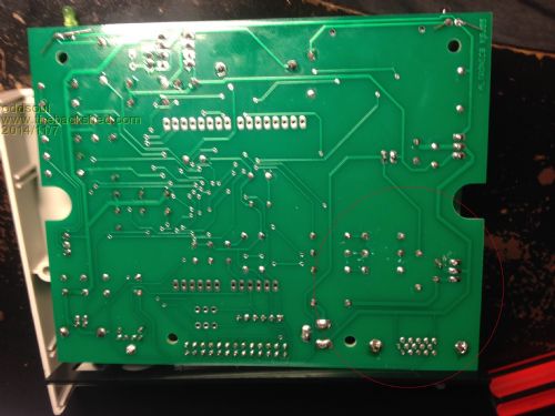
Thanks Jim, I don't have enough technical knowledge but have tried to find out the issue. I have 2 images of the PCB showing both sides of the board. - I have checked all solder points and they seem fine - Double checked resistors (The right value) - Diodes seem to be in the right orientation 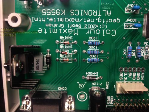
I'm not sure what a CRO is and I also don't have a multimeter that I can use to measure the outputs. Will try to find one otherwise please correct anything Eli |
||||
| TassyJim Guru Joined: 07/08/2011 Location: AustraliaPosts: 6538 |
Everything looks OK but my aging eyes have enough trouble checking resistor colour codes in the flesh, much less looking at a photo. Without a multimeter, testing gets a bit difficult. A CRO is an Oscilloscope, very helpful here. How are you powering the maximite? Can you test with a different monitor? The outputs from the processor swing from zero to 3.3 Volts. With a monitor connected (with 75 ohms input resistance) the monitor inputs would end up swinging between zero and 1.2 Volts. The diodes keep this from zero to 0.6 Volts. Because the output is mostly black, the voltages are mostly zero so using a multimeter will give a reading of close to zero. A CRO will show the brief high levels and this is what we need. If you draw a white box the full size of the screen, the output will be mostly white so the voltages will be mostly high. Now a multimeter can get a close representation of the high voltage level. Where are you located? There might be someone nearby who can help. Jim (Tasmania) VK7JH MMedit |
||||
BobD Guru Joined: 07/12/2011 Location: AustraliaPosts: 935 |
I copied the image, magnified it by 50% and I can read the resistors. They are (right to left in the image) Brown Red Black Black Gold = 120 ohms. The diodes are the correct way according to the overlay. In the absence of measurement, it's time to start substituting. Try a replacement cable and monitor. One sub at a time please. |
||||
| robert.rozee Guru Joined: 31/12/2012 Location: New ZealandPosts: 2529 |
hi, my suggestion is that you examine with a magnifying glass the soldering each side of pins 12, 53, and 72. these three pins are the colour signal outputs. a quick check of the colour maximite schematic shows the following adjacent pin functions: 11 - ? 12 - red video 13 - MCLR 52 - ? 53 - blue video 54 - Vbus 71 - D11 72 - red video 73 - bootload sw pins 11 and 52 are not shown on the schematic as far as i could see. cheers, rob :-) |
||||
| oddsoul Newbie Joined: 05/11/2014 Location: AustraliaPosts: 5 |
Thanks guys, I will be checking the cable and monitor tonight (Have already tried a HP monitor and it wouldn't even get a signal). As for the power supply, I use a 12V supply. The only thing I am concerned about is the amount of heat being generated on the 7805 VR. Even with the heatsink in place it seems to be burning the board a little bit. Should I be using a lower voltage supply? Will try all of the above suggestions shortly with an update to follow. Also someone wanted to know where I was. I am located in Perth, WA. Eli |
||||
Grogster Admin Group Joined: 31/12/2012 Location: New ZealandPosts: 9975 |
7805 should get reasonably warm, but no so hot as to scorch the PCB - something not quite right there. Are you able to put a multimeter in series with the power supply to the unit, and measure it's current consumption? Current consumption of my CG-CMM units is about 76mA. I have an Altronics unit around here somewhere - I will see if I can find it an measure it's current. EDIT: Found my Altronics kit. Current consumption is 157mA. Please check that your one sucks about the same amount of juice. Smoke makes things work. When the smoke gets out, it stops! |
||||
| robert.rozee Guru Joined: 31/12/2012 Location: New ZealandPosts: 2529 |
please check to see that R1 (10 ohms) is not getting hot. also look for any other components that may be overheating using your finger as a heat sensor. given that you are seeing an image on screen, this indicates the processor is running and that the heat being dissipated by the 7805 will therefore be matched by a similar quantity of heat at another component. look at IC4 (DS1307 real time collect) and check that it is the correct way round (matching the image on this page: http://www.geoffg.net/MaximiteDesign.html ). if reversed, it will generate heat/smoke. you really do need a cheap multimeter, the cheapest of cheapest digital meter from your local hardware store or ebay: http://www.ebay.com/itm/221513043874 rob :-) |
||||
| oddsoul Newbie Joined: 05/11/2014 Location: AustraliaPosts: 5 |
Alright, Have had a chance to check the monitor and cable -Different monitor had more of an issue with brightness -Cable didn't change anything Fixed the overheating issue -There was a small piece of metal contacting between the legs of the 7805VR Checked pins 12, 53, and 72 and saw no issues there.. Might need to wait till I get a multimeter :( Any other suggestions |
||||
| Geoffg Guru Joined: 06/06/2011 Location: AustraliaPosts: 3362 |
Hi Eli, I live in Perth (Kensington to be precise) and I should certainly be able to help. Drop me another email or PM if you would like me to look at it for you. As you would expect, I have a lot of test equipment. Geoff Geoff Graham - http://geoffg.net |
||||
| oddsoul Newbie Joined: 05/11/2014 Location: AustraliaPosts: 5 |
Well after all this time the issue was finally fixed New Resistors: 
Old Resistors:
If you look at the resistors in both images they were setup in the wrong orientation -120Ohm were in place of the 10K and that was why the video output and clock were not working Thanks to Geoffg for helping me with the issue. I think we all need to stop and look and look again so we make sure that these things don't happen! But it still was a good experience!! Now i'm off to program! Eli |
||||
| TassyJim Guru Joined: 07/08/2011 Location: AustraliaPosts: 6538 |
Good to see it working. A multimeter would be a useful investment! Jim VK7JH MMedit |
||||
| JohnS Guru Joined: 18/11/2011 Location: United KingdomPosts: 4335 |
A cheap meter can be had for next to nothing on ebay, even buy it now. I bought a spare and another that is in the car "just in case". John |
||||
| The Back Shed's forum code is written, and hosted, in Australia. | © JAQ Software 2026 |
