
|
|
Forum Index : Microcontroller and PC projects : Inductive sensors?
| Author | Message | ||||
| MM_Wombat Senior Member Joined: 12/12/2011 Location: AustraliaPosts: 139 |
Hi All, I am working on turning an old Laser cutter, made by Universal Laser Systems, in Arizona USA, that caught fire, into a CNC controlled machine. It has none of the old major electronics, or Laser, but some of the internal sensors, are still there. I plan on using it for many things. 3D printer, engraver or prototype circuit board driller/engraver. My question is about the inductive sensors that are already installed on the machine, for the limits. The sensors have no markings or visible codes. They have 3 wires, I assume, 1 for power (Vcc), 1 for earth(Ground) and 1 for return signal. Would the Vcc be 5V or 12V? Most of the ones I have looked at online range from 5V to 24V. One board has two sensors but only four wires, I assume 1 for Vcc, 1 for Ground, and 2 for sensor returns... AussieWombat Keep plugging away, it is fun learning But can be expensive (if you keep blowing things up). Maximite, ColourMaximite, MM+ |
||||
TassyJim Guru Joined: 07/08/2011 Location: AustraliaPosts: 6538 |
They could be hall effect sensors. Some I have are rated at anywhere from 3V to 24V A flow meter from Jaycar has: Specifications � Supply voltage : 2.4 - 26VDC � Supply current :Typical 3mA, maximum 6mA. � Output mode: Open collector � Output rise time: Typical 1second (max 10 seconds) � Output falling time: Typical 0. 3 seconds. (maximum 1.5 second) I would start with 5V. Jim VK7JH MMedit |
||||
| Gizmo Admin Group Joined: 05/06/2004 Location: AustraliaPosts: 5182 |
I have 3 of those proximity sensors on my CNC table. Cant tell you the wire colours, or how they are connected, as they are wrapped in heat shrink and joined to other different colour wires. But I think the sensors are pretty robust, so if you wire them wrong, they just wont work until you get them right. Mine were open collector output, and have a tiny LED embedded in the back where the wires come out. The LED lights when the sensor is close to metal. If yours have the tiny LED, I would power them up with a 5v supply in series with a 100R resistor, and try different combinations till it works. If no luck, try 12v. Glenn The best time to plant a tree was twenty years ago, the second best time is right now. JAQ |
||||
| MM_Wombat Senior Member Joined: 12/12/2011 Location: AustraliaPosts: 139 |
@ Gizmo & TassyJim Thank you for your prompt answers. Oops, seems I was incorrect in my evaluation of the sensor. The reason I could not see any markings was because of the soot from the fire. I noticed on a piece of the machine, that was not installed at the time, namely the rotary tool, there was one of the sensors. It is an EE-SX1042 from Omron. DataSheet : Info 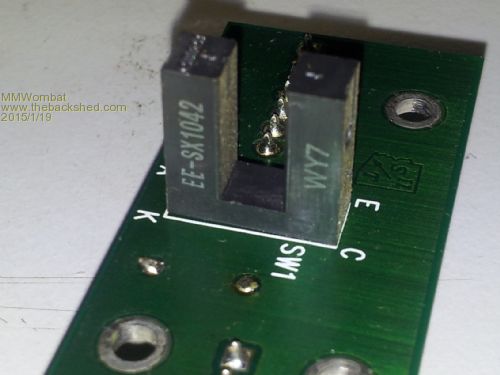
My understanding of the data sheet : Note 2, is that it requires a pulse. Would this be suited to a MM II to drive the sensor circuit for the cnc driver? How would I set it up? At the moment I can live with soft limits, set in the software, but a hardware backup, would be double safe.. If it is a PhotoMicroSensor, would the soot have damaged it, and would require replacing? There are three the same size, Z table limit ( Top and Bottom ), and Y Zero limit, and 1 tiny one for the X Max Limit. The machines inside (ambient to the sensor) would have to be around 80-100 Celsius to stop the ABS plastic printed part from warping. Would that mean I should look into a different sensor? AussieWombat Keep plugging away, it is fun learning But can be expensive (if you keep blowing things up). Maximite, ColourMaximite, MM+ |
||||
| Pete Locke Senior Member Joined: 26/06/2013 Location: New ZealandPosts: 184 |
How big are they? and what casing are they in? If they have the standard proxy colour cable, then Brown= B+, Blue= B- and Black= signal. Assuming (bad phrase :-) they are limit devices and there is a white wire, it won't be connected to anything. If they are a standard reed switch then their state can be changed with a magnet and seen with a volt meter (or low wattage panel lamp) connected to the blue and black wires. Don't know what to advise regarding supply voltage. If you can put up a picture of them then identification would be made a lot easier. Cheers Pete'. |
||||
| MM_Wombat Senior Member Joined: 12/12/2011 Location: AustraliaPosts: 139 |
@ Pete Locke Pete , I was just doing that when you posted. See previous post.. AussieWombat Keep plugging away, it is fun learning But can be expensive (if you keep blowing things up). Maximite, ColourMaximite, MM+ |
||||
centrex Guru Joined: 13/11/2011 Location: AustraliaPosts: 320 |
Hi wombat By the silkscreen on the board they are photo diode type the A K are a led the E and C are the emitter and collector of a transitor. There probably is a resistor in series with the A or the K on the board. The E is probably connected to gnd and the C to something else via a resistor. Hope this is of use. Regards Cliff The data sheet shows how to connect the device. Cliff |
||||
Grogster Admin Group Joined: 31/12/2012 Location: New ZealandPosts: 9975 |
I agree with Centrex. I have used heaps of these kind of photo-detector, and they are very easy to use and incorporate into a circuit - most of the time. Here is a circuit I built using one of these type of thing: 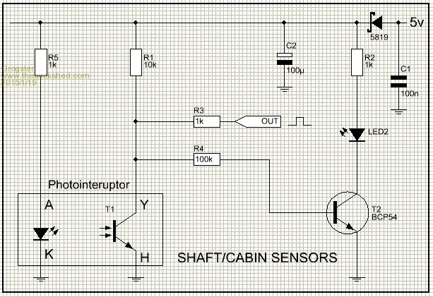
In "Normal" operation, the IR LED in the photo-interrupter is lit, and this causes the transistor in the photo-interrupter to switch on, pulling the output low. This also pulls the base of T2 low, keeping LED2 off. Whenever something interrupts the IR beam, the transistor will switch off, and the output to the MCU will go high. T2 is only there as an inverter/buffer for the LED to show when the beam has been broken, but it is not needed, strictly speaking. EDIT: To clarify - transistor T2 and LED2 are not really needed - I just put them on the circuit for the hell of it at the time, and you don't need R4, T2, LED2 and R2 unless you want the red LED to light whenever something gets in the path of the photo-interrupter. Smoke makes things work. When the smoke gets out, it stops! |
||||
| MM_Wombat Senior Member Joined: 12/12/2011 Location: AustraliaPosts: 139 |
@ Grogster Here is a small schematic that I took from the PCB. 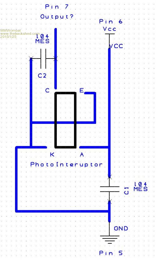
If I wanted to use this in the 3D printer, as a limit switch, would I join the output (pin 7) to the servo driver board(HY-TB5DV-M_5Axis_Driver), as active low or active high? Is it a constant voltage or pulse? What COULD the VCC be? Thanks in advance AussieWombat PS. I got the machine to draw a picture, much like engraving. At the moment it is working with softlimits. A short 3 minute video (41.3 Mb) is here Keep plugging away, it is fun learning But can be expensive (if you keep blowing things up). Maximite, ColourMaximite, MM+ |
||||
| TassyJim Guru Joined: 07/08/2011 Location: AustraliaPosts: 6538 |
I am surprised that there is no limiting resistor in the diode side. I would start with 1K to 5V as in Grogster's circuit and measure the current - aim for 20-30mA. On the photo transistor side, a 10k to 5V or 3.3V (same as Grogster's again). The output should be low when there is nothing in the light path and high when interrupted. Which way around that is depends on the physical setup of your machine. Jim If you can get it to PLAY the guitar, I would be really impressed. VK7JH MMedit |
||||
| Grogster Admin Group Joined: 31/12/2012 Location: New ZealandPosts: 9975 |
I concur with Jim - odd that there does not seem to be any LED limiting resistor. I guess it could(must?) be on the mainboard. "Pin 7 Output?" - I expect not. Unless you are making pin 7 on the MM, and INPUT. Generally speaking, photo-interrupters like this, are USUALLY all connected as an input device - I have never seen one as an output device. The concept is that you are using the interrupter to signal to the MCU, that the IR beam from the LED has been broken by something physical getting in the way. You are not actually switching the current to any motor or servo etc with the interrupter. It is then up to the MCU and code to decide how to handle that event. EDIT: It depends on how you wire the circuit. The transistor in the photo-interrupter will switch on through the C-E path, when the IR light from the LED hits it, and it will switch off when there is an obstruction in the IR beam. In my circuit above, the input to the MCU is normally low - being pulled low by the photo tranisistor in the interrupter. If something interrupts the IR beam, the photo transistor switches OFF, and the 10k/1k resistors pull the MCU input to 5v or so - the MCU input goes high whenever the IR beam in the interrupter is broken. The output of pin7 on your module will be constant. No interruptions to the IR beam: photo transistor conducts via C-E path. Interrupted IR beam: photo transistor does not conduct via C-E path. The safest method is to use the interrupter to signal the MCU, which then controls the servo driver. Smoke makes things work. When the smoke gets out, it stops! |
||||
| MM_Wombat Senior Member Joined: 12/12/2011 Location: AustraliaPosts: 139 |
The Pins are from the small circuit board, that controls the rotary unit. It has 7 pins. the first four are for the servo motor, and the last three, are for sensing the start point for the rotation. I do not plan on using this unit, but similar photointeruptors are used for the X, Y and Z limits in the machine. I haven't checked on the Z limit ones yet, but the X and Y have resistors on the board, just can't see values for soot.. Here are some pictures from the Driver board DOC file. I can put up a link to it if needed. Firstly the driver board. 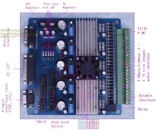
and the pinouts for the D-Subs. 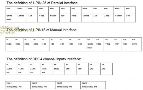
I would assume, I would take the 5V Vdd and ground from the 15 pin D-Sub, and join the wire from the 'C' side of the Photointeruptor to the corresponding input on the 9 pin D-Sub. Then set the control to 'Active High'. OR Easier just use some micro-switches as the limit switches.. on the 9 pin D-Sub Connecting each pair (P1 and P6, P2 to P7 etc) through the micro-switches (Normally Open) for each axis. Upper and lower limits in parallel. AussieWombat Keep plugging away, it is fun learning But can be expensive (if you keep blowing things up). Maximite, ColourMaximite, MM+ |
||||
| The Back Shed's forum code is written, and hosted, in Australia. | © JAQ Software 2026 |
