
|
|
Forum Index : Microcontroller and PC projects : SkinnyMite 1A...
| Author | Message | ||||
Grogster Admin Group Joined: 31/12/2012 Location: New ZealandPosts: 9975 |
Hiya. 
Congratulations on passing your 101. 
- LED Gree dots: Yes, on those LED's the green dots are cathode, and the silkscreen is marked with a dot for the Anode. Sorry if that caused confusion. I did the silkscreen on the PCB before I actually ordered the LED's, so assumed they would be polarity marked as Anode. But when you think about it, standard LED's have the flat on the Cathode side, so perhaps they borrowed from that idea? Not sure about other brands of SMD LED's, but I would hope and expect at this point, that the marking is always for Cathode.... Version 1B of this board has that fixed, along with the legend errors and the bloody regulator input error. 
- Supervisory is MCP130-315. It is a typo on the silkscreen and BOM as MCP140. This too has been fixed for 1B boards, and the BOM. How did you find positioning the PIC32? This is the bit that takes the most time, as you have to be very accurate, with only 0.5mm pin-pitch, and it really needs to be as perfect as possible to ensure correct alignment. A tiny mis-alignment is allowable, but you DON'T have much breathing room! 
I have found the best way to align the chip now, is to place the chip roughly where it needs to be, then use a small length of sellotape or insulation tape, and press it down on top of the chip. Now, rotate the ends of the tape, and the chip will move with the tape. Line it up where it needs to be as precisely as possible, and press the tape down onto the board. Double check everything is OK, then solder the adjacent sides of the chip from the tape. Remove the tape, and solder the other two sides. This works well for me, but others probably have other methods that suit themselves. Smoke makes things work. When the smoke gets out, it stops! |
||||
disco4now Guru Joined: 18/12/2014 Location: AustraliaPosts: 1127 |
I used some invisible sellotape cut down the center to make it not so wide. I used this over the chip to position it and stuck it down, I found I could get a fine adjustment by pressing the sellotape with the point of the tweezers where it left the board to straddle the chip. Once its lined up it soldered pretty easily. F4 H7FotSF4xGT |
||||
| WhiteWizzard Guru Joined: 05/04/2013 Location: United KingdomPosts: 2991 |
The way I teach SMD soldering (for TQFPs) is as follows: 1> Place a blob of solder shorting out 2 adjacent pins in one corner (i.e. pin 1 & pin 2). 2> Position the TQFP chip into place while heating the blob of solder (Use a low power iron; or low temp setting; to avoid heat damage to the PCB tracks). If you don't initially line the pins & tracks up then simply reheat the solder blob and 'tweak' into the correct position. Practice makes perfect - takes only a second or two once perfected. 3> Now solder a blob into the opposite corner to hold down the chip securely (pins already lined up from step above). 4> Now put plenty of solder across all pins (starting on a third side to avoid the TQFP from 'twisting' out of position). DON'T try and solder each individual pin, instead short out all pins with enough solder. 5> Put some flux fluid onto a piece of desolder braid. Place braid into one side/row of pins and use the side of the soldering-iron tip to heat braid. Solder will flow into braid leaving a very neat row of solder joints. IF any pins are shorted out still then simply repeat above process with flux and fresh braid to remove the short(s). 6> Repeat for all four sides. The above process does take about 5 TQFPs to master but then it will take about 1minute to very neatly solder a TQFP down to 0.4mm pitch. The above is just a method I found best after I had tried the tape method. There is no right or wrong way (apart from ensuring no shorts or open circuits) - as Grogs says; its whatever works best for you! Just sharing my method in case others wish to delve into SMD soldering of these packages. WW |
||||
| MicroBlocks Guru Joined: 12/05/2012 Location: ThailandPosts: 2209 |
There are many ways to solder a tqfp. I started with a very fine tipped low wattage solder iron and did the pins one by one. I have good eyesight for closeup so that worked ok. The reason i did it like that was because i was afraid to shorten the pins and had to do a cleanup. Worked fine but took ages. Now i just use a big tip, put some flux on the pins and load the tip with solder and just drag it along the pins. 5-10 seconds per side including putting on flux. Often 1 or 2 pins are shorted (i am not that good yet) but just a quick touch and moving the tip outward quickly to 'scoop up' the solder. Took some practice but hardly have to do any cleanup. I saw this technique used on a youtube video (https://www.youtube.com/watch?v=5uiroWBkdFY&t=118) and was impressed, and i just kept trying until i got it right. I guess it took a few days and about 30-40 tqfps. Got some desoldering and cleanup experience thrown in for free. :) Move the video to the start to see some other styles. Microblocks. Build with logic. |
||||
| Justplayin Guru Joined: 31/01/2014 Location: United StatesPosts: 330 |
Wow! That guy makes SMD soldering look incredibly easy. Almost makes me believe I could do it. --Curtis I am not a Mad Scientist... It makes me happy inventing new ways to take over the world!! |
||||
| Grogster Admin Group Joined: 31/12/2012 Location: New ZealandPosts: 9975 |
Yeah, it's really quite easy, even right down to 0.5mm, once you have had a little bit of practise. There was a time, I would not touch ANY surface-mount. If it had SMD on it, then I would look for another project. I came around to SOIC first, with it's 1.27mm pin pitch, then 0.8mm QFP's and most recently, the 0.5mm QFP's. Having now done a few 0.5mm QFP's, SOIC looks like a HUGE pin spacing, and I now wonder why I was so frightened of SMD. To paraphrase you for a moment, SMD IS incredibly easy - once you know how, and videos like the one TZA linked to are fantastic, as they let you see up close, just how easy it really is. Once you have the chip in the right place, soldering these things is usually FASTER then any through-hole equivalent. Passives excluded. I use the sweep method in that video, and nice to see they too use the same tape idea to hold the chip where it needs to be. I will have to had a go at drag-soldering next time - it is the fastest per-side. Smoke makes things work. When the smoke gets out, it stops! |
||||
| WhiteWizzard Guru Joined: 05/04/2013 Location: United KingdomPosts: 2991 |
Grogs, Currently building some Skinny's (without the reset support IC as none to hand) and am now pondering something. So maybe a silly question; but what is the latest MX470 beta version that runs correctly on the Skinny v1A? I ask because I know matherp swapped some pins around recently and I'm too tired to recollect if this has an impact on the I2C pull-ups on your PCB. I will try load B10 for now but would appreciate your recommendations . . . Thanks! WW |
||||
| Grogster Admin Group Joined: 31/12/2012 Location: New ZealandPosts: 9975 |
As far as I know, the latest beta should work. I am using B9. I have not tested any I2C stuff yet, and don't recall any changes here, but I will have to check. The notes ODT file in the document download should say if there were any changes there, if you check the current pinout. EDIT: Just compared the 1A with the latest pinout, and the I2C pins have not moved, so that should work as labelled on the silkscreen with pins 43 and 44. Smoke makes things work. When the smoke gets out, it stops! |
||||
Lou Senior Member Joined: 01/02/2014 Location: United StatesPosts: 229 |
Grogs, I got my skinnyMite boards today, Thank you. I'll try to build them all up tomorrow and let you know. I got the part of the Coke carton that says "Sugar Free" so I can verify you're not on the hard stuff. Lou Microcontrollers - the other white meat |
||||
| MicroBlocks Guru Joined: 12/05/2012 Location: ThailandPosts: 2209 |
They arrived in Thailand today.:) Right on time before the weekend, great! This board has very sharp letters. Did you use vector or TTF? And what font and size. Small and good readability. I am impressed. Microblocks. Build with logic. |
||||
| Grogster Admin Group Joined: 31/12/2012 Location: New ZealandPosts: 9975 |
Hey TZA.
It is just whatever font is built into Sprint Layout 6. You can't change the font, from what I can see. Always seems to work out fine on the boards, so I have never wanted to change the font. The tiny print is 1mm in size - you specify the size of the text in mm, rather then pitch like with a word-processor. Smoke makes things work. When the smoke gets out, it stops! |
||||
| MicroBlocks Guru Joined: 12/05/2012 Location: ThailandPosts: 2209 |
I got most parts soldered but can not test yet as the 100n capacitors i have do not fit.
Microblocks. Build with logic. |
||||
| Grogster Admin Group Joined: 31/12/2012 Location: New ZealandPosts: 9975 |
Heh, heh. Are they 0603's? Smoke makes things work. When the smoke gets out, it stops! |
||||
| MicroBlocks Guru Joined: 12/05/2012 Location: ThailandPosts: 2209 |
Yes (I still have a few thousand of those...). I am trying to find the 1206 but i can only order a minimum of 4000. Have to go look for some more places that sell them. Maybe i just extend the pads a bit with some wire, that will be an interesting experiment. Microblocks. Build with logic. |
||||
| WhiteWizzard Guru Joined: 05/04/2013 Location: United KingdomPosts: 2991 |
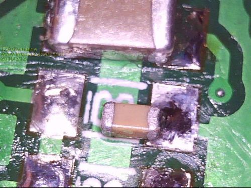
But most caps are grounded one side (with ground plane under the cap). Simply solder the NON-Gnd pad directly to the cap, then a wire (or solder blob) to the GND pad (this is what I did successfully on my first Skinny!)
WW edit: so in your photo; desolder the cap, solder to the other pad, and then a 'blob' of solder to the other pad . . . Just allows you to begin testing; not a recommended/tidy solution |
||||
| MicroBlocks Guru Joined: 12/05/2012 Location: ThailandPosts: 2209 |
i have to look at the traces a bit more but i think it can be done by scraping of a bit of soldermask and use a gnd trace/fill nearby. the top two have gnd on the right, the bottom two on the left. so i can rotate the second one from the top 90 degrees, the top most i can gnd by using the pad from the big xr5. leaving only two that need an alternative gnd. Should work....... Microblocks. Build with logic. |
||||
| WhiteWizzard Guru Joined: 05/04/2013 Location: United KingdomPosts: 2991 |
TZA, don't bother with scrapping (or scraping  ) the PCB, just use the surface tension of the solder to 'short' the cap to the GND pad. Only thing to be wary of is to use a low temp, or low power iron otherwise too much heat then 'melts' the other end (i.e. the non-gnd joint). ) the PCB, just use the surface tension of the solder to 'short' the cap to the GND pad. Only thing to be wary of is to use a low temp, or low power iron otherwise too much heat then 'melts' the other end (i.e. the non-gnd joint).
I start by soldering one end of the cap directly to the non-gnd pad, then put lots of solder on the gnd pad and 'push' it to the unsoldered end of the cap (this minimises heat in the cap and results in it remaining in place). I also use metal tweezers to act as a 'heatsink' to minimise heat melting the first solder joint. Persevere - it does work (I often solder wrong size parts onto pads - FOR MY OWN USE only!) |
||||
| Grogster Admin Group Joined: 31/12/2012 Location: New ZealandPosts: 9975 |
@ WW - An interesting approach. 
@ TZA - Element14 sell 100n caps for 3c each, MOQ=1 Smoke makes things work. When the smoke gets out, it stops! |
||||
palcal Guru Joined: 12/10/2011 Location: AustraliaPosts: 2039 |
Got my Skinny-Mite up and running with a 64 pin chip. The Banner did come up once after about 5 secs. then came up again and then it settled down to a flashing cursor. I wrote a short test program and it works as expected, but I haven't seen the Banner on start up since. Paul. Edit. does come up if I run CPU RESTART so not a problem. "It is better to be ignorant and ask a stupid question than to be plain Stupid and not ask at all" |
||||
| The Back Shed's forum code is written, and hosted, in Australia. | © JAQ Software 2026 |
