Notice. New forum software under development. It's going to miss a few functions and look a bit ugly for a while, but I'm working on it full time now as the old forum was too unstable. Couple days, all good. If you notice any issues, please contact me.
easterly81 Newbie Joined: 08/04/2015 Location: United StatesPosts: 15
Posted: 10:36pm 07 Apr 2015
Copy link to clipboard
Print this post
Hello
I am confused about the structure of the PWM command. I was currios if anyone could explain how to use it or provide me with an example.
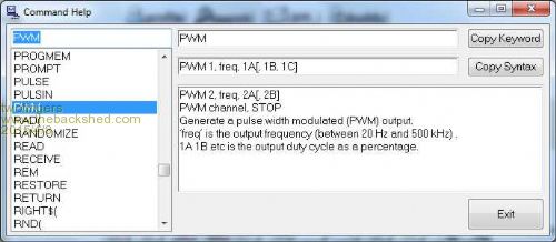
From mmedit
How do you specifie pins? mkII has pwm 1a,1b,2a,2b,and 1c What is the difference between a,b,c?
Thanks
twofingers Guru Joined: 02/06/2014 Location: GermanyPosts: 1752
Posted: 11:17pm 07 Apr 2015
Copy link to clipboard
Print this post
Hi easterly81
uM Manual p.12
The pins on a 28-pinner are 4,5,6 (PWM 1a-1c) and 26, 24 (PWM 2a+2b).
Geoff only knows! I guess there is no difference between a,b,c. But you can set the pulse width for any subchannel independently (PWM 1, freq, 1A, 1B, 1C ).
I didn't know about the MMedit-Help till today:
You will find more info on page 54 of the uM MMbasic manual.
Regards and welcome
MichaelEdited by twofingers 2015-04-09causality ≠ correlation ≠ coincidence
Grogster Admin Group Joined: 31/12/2012 Location: New ZealandPosts: 9975
Posted: 11:18pm 07 Apr 2015
Copy link to clipboard
Print this post
Hi.
As an example:
PWM 1,20000,100,50
This command will set PWM channels 1a and 1b using a 20kHz frequency.
PWM 1a will be 100, and PWM 1b will be 50
Does that help?Smoke makes things work. When the smoke gets out, it stops!
easterly81 Newbie Joined: 08/04/2015 Location: United StatesPosts: 15
Posted: 03:52am 08 Apr 2015
Copy link to clipboard
Print this post
Yes thanks
So Can you set 1c by PWM,1,20000,100,50,x
with x being the duty of 1c?
Thanks
Grogster Admin Group Joined: 31/12/2012 Location: New ZealandPosts: 9975
Posted: 04:28am 08 Apr 2015
Copy link to clipboard
Print this post
Yes, you can.
Only works for channel 1 though, as channel 2 just has the two PWM outputs.
The beauty of doing the PWM this way on a one-channel-per-command basis, is you could have up to five PWM signals all going at the same time, with different pulse-widths.
I've never actually needed that many, but two at once for controlling those PWM motor controller modules from eBay certainly has made my life easy.
...and like twofingers said: welcome aboard the good ship TBS forum.
EDIT: BTW, you asked in post #1 about specifying the pins. This is set by MMBASIC, and you cannot specify them yourself. With the 28 pin chip, the PWM channels are set like this:
So, if you wanted to setup a PWM on 1C, you would specify something like:
PWM 1,20000,100,100,X - where X is the PWM value you want.
In the above example, PWM 1A and PWM 1B are set as 100, which essentially sets those outputs to an "Always on" state. If you were to set them to zero, they would have a very narrow pulse-width, which if used with a motor controller, normally means full-speed.Edited by Grogster 2015-04-09Smoke makes things work. When the smoke gets out, it stops!
WhiteWizzard Guru Joined: 05/04/2013 Location: United KingdomPosts: 2991
Posted: 09:00am 08 Apr 2015
Copy link to clipboard
Print this post
Something worth noting (as I eventually discovered the other day):
If you only need one PWM line, then it is preferable to use 1A (or 2A) as opposed to 1B/2B or 1C. The reason being: if you were to use 1C for example AND are also using pins 4 and/or 5 for other functions (i.e. digital I/Os) then when you set up your duty cycle on 1C with the PWM command you HAVE to set a duty cycle for 1A and 1B too (i.e. you can not use 'PWM 1,freq,,,1C' with 'blanks' for 1A and 1B. So using a value to set up the duty on 1C will involve a command such as 'PWM 1,2000,50,50,100' which in turn changes Pins 4 and 5 to PWM signals (i.e. they are no longer whatever function they were prior to the PWM command being issued).
I hope this all makes sense - and maybe saves some of you a few hours head-scratching
WW
Grogster Admin Group Joined: 31/12/2012 Location: New ZealandPosts: 9975
Posted: 03:18pm 08 Apr 2015
Copy link to clipboard
Print this post
An excellent point, WW - nice one.
Totally agree, and if easterly81 only plans to use 1C, then perhaps swap pins and use 1A, to paraphrase you for a moment...Smoke makes things work. When the smoke gets out, it stops!
WhiteWizzard Guru Joined: 05/04/2013 Location: United KingdomPosts: 2991
Posted: 05:09pm 08 Apr 2015
Copy link to clipboard
Print this post
Sorry that I forgot to mention the main point in my previous post . . .
So if using one PWM line, then by using 1A (pin 4) you can use the command PWM 1,freq,duty (i.e. not have to state values for 1B or 1C). This then leaves pin5 (1B) and pin6 (1C) 'untouched' i.e. the same function as they were before the PWM command is encountered.


 I guess there is no difference between a,b,c. But you can set the pulse width for any subchannel independently (PWM 1, freq, 1A, 1B, 1C ).