
|
|
Forum Index : Microcontroller and PC projects : AD9833 DDS Signal Generator
| Author | Message | ||||
boss Senior Member Joined: 19/08/2011 Location: CanadaPosts: 268 |
Hi, If someone of you is interested to build nice DDS Signal generator cover 1Hz to 12.5Mhz for less than $10, there is description how to do it: Couple weeks ago I found nice AD9833 module with amplified output on eBay for $9.50 and free shipping. Simply connect the module with uMiteII via 3(SPI) wires (see instruction in DEMO programm) and 5V power, download the enclosed "DEMO" and enjoy.Because of DDS you must add the LP filter to reconstruct signal properly. Right now I'm working on LP filter design. 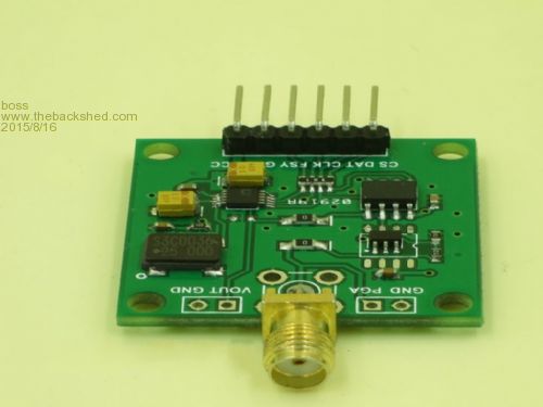
--------------------------------------------------------------------- Option COLOURCODE ON 'AD9833 SIGNAL generator 1OHz -12.5MHz|uMiteII chip=MX170, FW 4.7b23 Fsyn= pin 6,Clk=pin 25,Data= pin 3 Option Explicit Option default Integer CPU 40 Const RstOn= &H2100 Const RstOff=&H2000 Const CS=5 Const Fsync=6 'AD9833 Pins Defition Pin(CS)=1 SetPin CS,dout Pin(Fsync)=1 SetPin Fsync,dout Dim PK! Dim Phase = 0, Phase0 = &HC000, Phase1 = &HE000 Dim Freq , Freq0 = 1000000, Freq1 = 2000000 Dim Konst = 100000000 Dim Vak = 1073743824 '1073741824 Dim FreqH, Cislo1=&H575A, Cislo2=&H428F, Cislo3 Dim TunningWord$, TWL$,TWH$ '__________________________________________________________________________ AD9833_update 'First run '**************************** Main ***************************************** 'Starting frequency Do Input "Enter desired Frequence (10Hz - 12.5MHz): ",Freq If Freq > 12500000 Then Freq=12500000 If Freq < 10 Then Freq=1000000 Cislo3 = (Freq * Vak)/Konst TunningWord$=Hex$(Cislo3) Cislo1=Cislo3 And &H3fff FreqH=Cislo3 >> 14 Cislo2=FreqH And &H3fff Do PK!= Len(TunningWord$) If PK! <7 Then TunningWord$= "0"+TunningWord$ 'Print "PK!="; PK! Loop Until PK!>6 Print"====================================================================" Print Freq%;"Hz","Tword ";Cislo3%;" Dec ";,TunningWord$;" Hex" Print"--------------------------------------------------------------------" Print "Tuning Word High 14bit Dec ";" TWordH ";Cislo2%,"TWordL ";Cislo1% Print "..................................................................." TWH$=Hex$(Cislo2%) Do PK!= Len(TWH$) If PK! <4 Then TWH$= "0"+TWH$ 'Print "PK!="; PK! Loop Until PK!>3 TWL$=Hex$(Cislo1%) Do PK!= Len(TWL$) If PK! <4 Then TWL$= "0"+TWL$ 'Print "PK!="; PK! Loop Until PK!>3 Print "+++++++++++++++++++++++++++++++++++++++++++++++++++++++++++++++++++" Print " AD9833 Signal Generator (SINE,TRIANGLE,SQUARE) 12.5MHz Clock (eBay) " Print "+++++++++++++++++++++++++++++++++++++++++++++++++++++++++++++++++++" Print "Tuning Word: High (14bits) Hex: " TWH$;" Low 14bits Hex :",TWL$ Print "+++++++++++++++++++++++++++++++++++++++++++++++++++++++++++++++++++" ' 2^28 / MCLK ( for 25MHz it is about 10.73741824) 'Add &H4000 to LSB And MSB Cislo1=Cislo1+16384 Cislo2=Cislo2+16384 TWL$=Hex$(Cislo1) TWH$=Hex$(Cislo2) '---------------------------------- Print "RstOn= ",Hex$(RstOn),"Hex" Print "LSB = ",TWL$,"Hex" Print "MSB = ",TWH$,"Hex" Print "Phase=",Hex$(Phase),"Hex" Print "RstOff=",Hex$(RstOff),"Hex" AD9833_F1 Loop Sub AD9833_update SPI Open 10000000,2,16 Poke word &HBF805830,1 Pin(6) = 0 Pause 0.1 SPI WRITE 5, RstOn,CISLO1,CISLO2,Phase,RstOff Pause 0.1 Pin(6) = 1 SPI Close End Sub Sub AD9833_F1 SPI Open 10000000,2,16 Poke word &HBF805830,1 Pin(6) = 0 Pause 0.1 SPI WRITE 4, RstOn,CISLO1,CISLO2,RstOff Pause 0.1 Pin(6) = 1 SPI Close End Sub End Regards Bo |
||||
bigmik Guru Joined: 20/06/2011 Location: AustraliaPosts: 2979 |
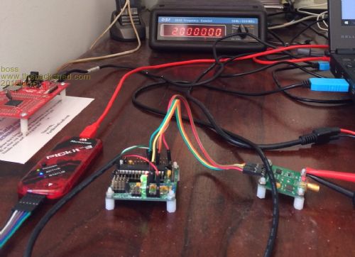
Hi Bo, I am about to show you how naive I am right now... What is the LP filter that is required and does this need to be different for every signal generated? Hey!!! I see one of my MuPs in that picture... Nice work. Regards, Mick Mick's uMite Stuff can be found >>> HERE (Kindly hosted by Dontronics) <<< |
||||
| boss Senior Member Joined: 19/08/2011 Location: CanadaPosts: 268 |
Hi Mike, Greeting from very hot Vancouver LP filter means Low Pass filter and consist of 5 inductors ~2uH,6 capacitors ~250pF and one resistor 200 Ohm. The design is finished but LP response need to be verified with signal generator and oscilloscope. Hopefully I can do it till end of this week. LP is connected to the DDS output connector. Existing SW is my test SW, but works a charm. Details how to connect display with touch screen and carved this rough software to the perfection is not major issue. Regards Bo |
||||
| boss Senior Member Joined: 19/08/2011 Location: CanadaPosts: 268 |
@Bigmik there is the filter design 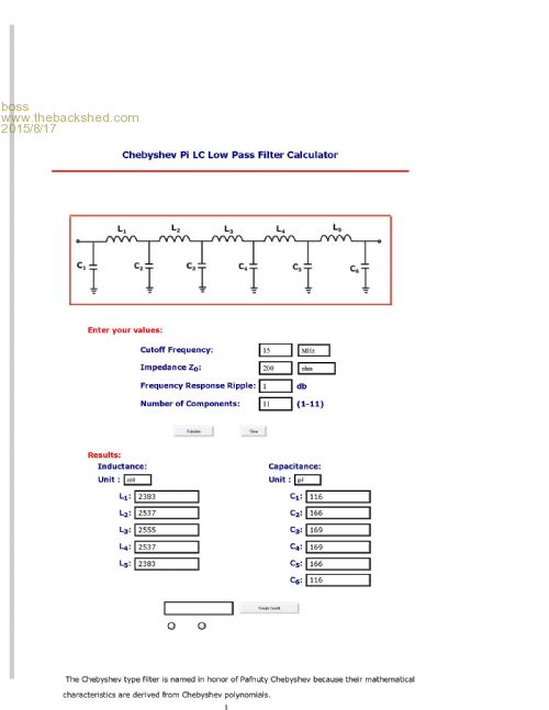
Bo |
||||
| bigmik Guru Joined: 20/06/2011 Location: AustraliaPosts: 2979 |
Ho Bohumil, Is that in series with the resistor? What sort of voltage level with this module put out? Mick Mick's uMite Stuff can be found >>> HERE (Kindly hosted by Dontronics) <<< |
||||
| boss Senior Member Joined: 19/08/2011 Location: CanadaPosts: 268 |
@bigmik No parallel to C6, but instead resistor I'm considering to use 200 Ohm potentiometer allows you control desired output level. For frequencies 1Hz-6250000 the output level is stable higher frequencies goes down with amplitude. Bo |
||||
geraldfryjr Regular Member Joined: 02/03/2014 Location: United StatesPosts: 61 |
Very Cool Project!!! I have a few different versions of these chips in my inventory. I have been wanting to get one working and this will help me a lot!! Thank You for posting this!!! jer  Keep on DIYin' !!!  |
||||
| boss Senior Member Joined: 19/08/2011 Location: CanadaPosts: 268 |
@geraldfryjr It is my pleasure. Please remember that command : Poke word &HBF805830,1 is there just temporary as Geoff fixed an error in the b23 FW and should be removed in future FW version. Bo |
||||
| boss Senior Member Joined: 19/08/2011 Location: CanadaPosts: 268 |
@bigmik MuP is a perfect tool for testing and development purposes. I really like it.
To the module signal: AD9833 can generate sinus, triangle and square signal. Sinus level p-p is around 3V for frequencies up to 6.25MHz, for higher frequencies the p-p level goes down. As simple and inexpensive signal generator is good enough. And there is possibility to ad another functionality ie. sweep generator just write the code. Regards Bo |
||||
| lstecher Newbie Joined: 23/04/2017 Location: United StatesPosts: 1 |
My first reply came back with an error message - so I apologize for this resend: I've been searching many forums and this post is the first I've found that uses the exact module with a AD9833 plus on-board amp that I have. I realize this is an old post, but I'd appreciate any information you have. I'm confused on the pin interface to the module and can't find any documentation other then for the AD9833 alone. The module has both SS/FSY and CS pins. Normally if there are multiple modules on the SPI bus, you just set each module with a different SS control pin to avoid collisions. Do you know why there are both SS and CS pins? Did you find some module specific documentation or just experiment? If you found documentation can you provide me a link? Also you set CS to HIGH and SS to LOW to set the registers in the AD9833 and then SS back to HIGH at the end of the set up. Why is CS HIGH - rather then a standard SPI setting of LOW to trigger module processing of the data? Thanks for any information. Lee |
||||
| Geoffg Guru Joined: 06/06/2011 Location: AustraliaPosts: 3353 |
Welcome to the forum Lee. The SPI interface has two chip select signals - FSY which, when taken low, addresses the AD9833 and CS which addresses the MCP41010 digital potentiometer (which is also in the module). This post presented a simple interface to the board: http://www.thebackshed.com/forum/forum_posts.asp?TID=8032 This web page describes a full function/sweep generator using the same board: http://geoffg.net/SignalGenerator.html And this magazine article described the project in more detail: http://www.siliconchip.com.au/Issue/2017/April/Micromite+BackPack+Touchscreen+DDS+Signal+Generator I never found a data sheet for the module itself. Geoff Geoff Graham - http://geoffg.net |
||||
| boss Senior Member Joined: 19/08/2011 Location: CanadaPosts: 268 |
Good morning everyone, the reason why I recall this (abandoned) project is the LP filter design. I spend several weeks with design and tuning LPF and then close project because of problem with signal quality at frequency higher than 10MHz. May goal was to have pocked generator covering range from 20kHz - 12MHz. The generator was finally build with AD9834 chip (75MHz clock) and is working fine. Later I decided I need to add an controlled attenuator and RF(RMS sine) millivoltmeter. When I saw Geoff's version of DDS generator I decided to build AD9833 vesion again. The frequency range problem was solved simply when replace 25MHz oscillator with 33MHz. The project is now in progress.I decided to use Geoff's code and add my extra HW (attenuator LPF and RF milivotmeter). And when I want to install LPF and test the signal generator I didn't find my LPF documentation. All my previous LPF work simply gone.  |
||||
| The Back Shed's forum code is written, and hosted, in Australia. | © JAQ Software 2026 |
