
|
|
Forum Index : Microcontroller and PC projects : RC filters for sound output....
| Author | Message | ||||
Grogster Admin Group Joined: 31/12/2012 Location: New ZealandPosts: 9975 |
Hi folks. 
There are two different RC circuits I use for either PICAXE or MicroMite. PICAXE ONE: 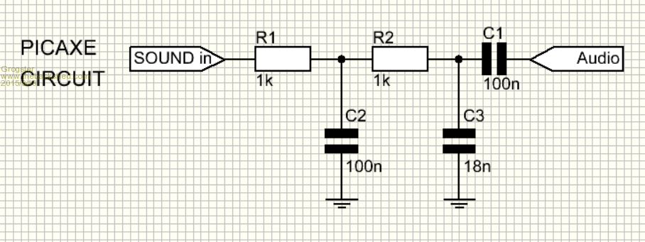
MICROMITE ONE: 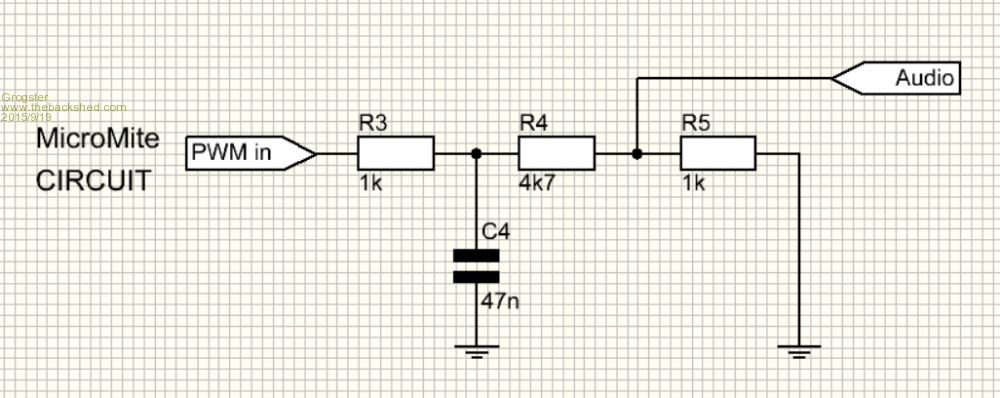
Are they both just as good as each other? Does one have merits over the other? I am curious about the two different designs, as the output from the PICAXE and the MicroMite are both PWM square-wave signals, so why the difference in circuit? I would like to standardize on one circuit. At this stage, I am using the PICAXE one as I figure that the 18n cap will further smooth out the square-wave, making it a better waveform for feeding into an amplifier. But having said that, the MicroMite circuit does not use the 18n, and still seems to work OK, so what are the options here? Smoke makes things work. When the smoke gets out, it stops! |
||||
| WhiteWizzard Guru Joined: 05/04/2013 Location: United KingdomPosts: 2991 |
Does either sound better than the other? At least with the PicAxe there is a cap prior to the (amp) audio input. This 'can' save power consumption in some circumstances so better in battery powered circuits. Lets see what the audiophiles say . . . . |
||||
| MicroBlocks Guru Joined: 12/05/2012 Location: ThailandPosts: 2209 |
From someone who is not that good with analog, so please check it. :) The picaxe will have out lower then 1600Hz and higher then 8850Hz. The Mite one about 3400Hz followed by a voltage divider to probably get it into the 1v peak to peak that most audio equipment expects. Check what different HZ actually sound like here: https://www.youtube.com/watch?v=igGroIcga3g Calculate the cutoff frequencies here: http://sim.okawa-denshi.jp/en/CRtool.php I think it is important to know what you will connect. A piezo buzzer or an amplifier, or just a small speaker. The capacitor before the output is to let only AC through. That is missing from the micromite one. Microblocks. Build with logic. |
||||
| Grogster Admin Group Joined: 31/12/2012 Location: New ZealandPosts: 9975 |
Connection to audio amplifier, which then drives any standard speaker. So, it is essentially needing to be filtered to make it suitable as a line-level input for any standard audio amplifier. I will check out the links. EDIT: The amplifiers I am using are these ones. They are cheap as chips, and work surprisingly well for the price and size of them. As per the PDF for the PAM8403, I add an external RF choke and cap for each speaker wire. These parts are not on the little PCB. Smoke makes things work. When the smoke gets out, it stops! |
||||
| The Back Shed's forum code is written, and hosted, in Australia. | © JAQ Software 2026 |
