|

|
Forum Index : Microcontroller and PC projects : SD activity LED for MM+?
| Author | Message | ||||
Grogster Admin Group Joined: 31/12/2012 Location: New ZealandPosts: 9874 |
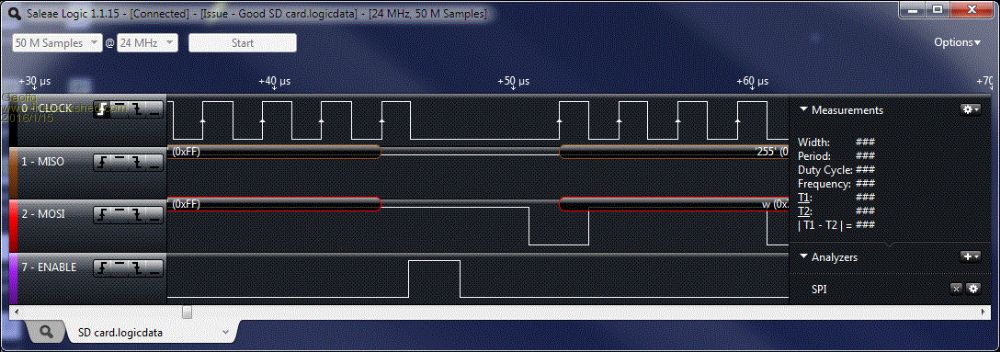
I have one of those Saelie 8-channel logic analyser things. Geoff would probably be the one to tell us how the SD is timed though. I can hook up the Saelie and run tests if you really want to know. Smoke makes things work. When the smoke gets out, it stops! |
||||
| atmega8 Guru Joined: 19/11/2013 Location: GermanyPosts: 738 |
Retriggereable Monoflop, NE 555, CD4538 (MC14538), 74HC123, 74HC423, 74HC4538.... and so on.. |
||||
| kiiid Guru Joined: 11/05/2013 Location: United KingdomPosts: 671 |
I think robert.rozee has summarised it about right. Maybe worth a short with another card first? Or playing a bit with the resistor value. It should work fine. http://rittle.org -------------- |
||||
| robert.rozee Guru Joined: 31/12/2012 Location: New ZealandPosts: 2492 |
with a bit of luck geoff will notice this thread and be able to offer some insight. while the Saelie may offer a few clues, it is probably not worth the effort until geoff chips in (or anyone else steps up with a MM+ and digital scope). the time delays could well be down at the tens of nanosecond level, which the Saelie would be hard pushed to show. i keep finding myself oh-so-tempted to splash out on one of those rigol ds1054z scopes, ideal for such occasions as this. but at the moment it is a luxury just a step too far! cheers, rob :-) |
||||
| Geoffg Guru Joined: 06/06/2011 Location: AustraliaPosts: 3340 |
I believe that the timing is correct. The lower trace shows CD (or -SEL) and it is deasserted at the end of the last clock pulse and reasserted 4uS before the next one. 
Geoff Graham - http://geoffg.net |
||||
| robert.rozee Guru Joined: 31/12/2012 Location: New ZealandPosts: 2492 |
it certainly does look like there is plenty of leeway, suggesting the problem when first using LED + 1k8 resistor may have been 'finger trouble' 
btw, geoff: what do you think of the Saleae logic analysers? i've never used one myself, but do see that clones can be had on ebay for about us$10. cheers, rob :-) |
||||
Grogster Admin Group Joined: 31/12/2012 Location: New ZealandPosts: 9874 |
So, it works OK with your change to the circuit, Rob, but the card won't respond with the series-LED method as posted by kiiid. I don't care, so long as it works, but can anyone say why that is? The series-LED is obviously the cause, but I still would have expect that when CS goes low, it would still pull SD-CS(pin1, full-size SD card) low enough to convince the card to respond. Oh well.... Smoke makes things work. When the smoke gets out, it stops! |
||||
| robert.rozee Guru Joined: 31/12/2012 Location: New ZealandPosts: 2492 |
you're running on 3v3, and the LED will have around 1.5v or so drop. so the CS pin is only being pulled down to about 45% of Vcc. this is at best extremely marginal for 'logic low'. if the SD card were running on 5v, then the level would be 30% of Vcc, which would have a better chance of working. this all assumes that the drop across the LED is only 1.5v, and not a little higher. i think kiiid just happened to strike a favourable set of component error margins, or was mistaken about which end of the LED he had attached pin 2 of J2 to. i've certainly made similar mistakes in the past, it is easy enough to do. cheers, rob :-) |
||||
Grogster Admin Group Joined: 31/12/2012 Location: New ZealandPosts: 9874 |
Acknowledged. Smoke makes things work. When the smoke gets out, it stops! |
||||
| Geoffg Guru Joined: 06/06/2011 Location: AustraliaPosts: 3340 |
I bought an original a few years ago for US$140 and it has been one of the best $140 that I have spent. The hardware is very simple, just one chip, which is why it has been cloned so much but it is the software that makes it a stand out. It is slick, easy to use and so productive. Because the data is logged to your PC you can record very long streams of data, up to tens of seconds and this is invaluable when you are searching for that elusive event on startup for example. It can log at up to 24MHz which is good for most stuff that we do and the software comes with a great range of analysers for SPI, serial, I2C, etc and that makes it very easy to decode a serial protocol. About the only downside is that eight channels is a bit limiting and the triggering options could be more sophisticated. Much later I bought one of the $10 clones to see what it was like and provide a backup in case I accidentally fried my genuine one. The clone worked exactly the same as the real thing - you, or the software, cannot tell the difference. I feel for the guy who designed the original and wrote the software. Now is the time if you do want to buy one of these. Apparently the maker of the chip used in the device is discontinuing production. Saleae may switch to an alternative chip which will require new software or they may just discontinue the Logic 8 because it has been cloned so much. Either way the supply of the cheap clones that work with the standard Saleae software will eventually dry up. Geoff Geoff Graham - http://geoffg.net |
||||
| kiiid Guru Joined: 11/05/2013 Location: United KingdomPosts: 671 |
True. I always forget about the damn drop  
The LEDs that I normally use are blue or white, and those have drops more or around 3V, not 1.5-1.8V as the red or green ones. http://rittle.org -------------- |
||||
bigmik Guru Joined: 20/06/2011 Location: AustraliaPosts: 2979 |
GDay Kon, Would that not make the situation worse? I see that if the LED dropped 3V then the Anode would be at 3V level when a LOW was applied by MM+, it would never work as shown. Most red and green LEDs have voltage drops of 2.1v these days. Regards, Mick Mick's uMite Stuff can be found >>> HERE (Kindly hosted by Dontronics) <<< |
||||
| kiiid Guru Joined: 11/05/2013 Location: United KingdomPosts: 671 |
What can I say? Yes, it is not supposed to work, but for some reason it did work on my board before. However it is NOT right. The correct way should be the output connected to the other side: + | A C | R MM+--+----CS http://rittle.org -------------- |
||||
Grogster Admin Group Joined: 31/12/2012 Location: New ZealandPosts: 9874 |
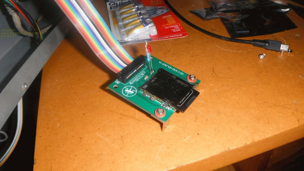
Yes, this is how I have it set now as Rob suggested, and it does seem to work OK that way. 
This is, naturally, a temporary testing setup!  Smoke makes things work. When the smoke gets out, it stops! |
||||
| The Back Shed's forum code is written, and hosted, in Australia. | © JAQ Software 2026 |