
|
|
Forum Index : Microcontroller and PC projects : circuit for pic32mx170/micromite
| Author | Message | ||||
| isochronic Guru Joined: 21/01/2012 Location: AustraliaPosts: 689 |
This is a generic circuit I use for a pic32mx170B, with a usb-serial bridge. From my reading of micromite threads I think it should work with the micromite/ MMBasic to a large extent - so I am asking those in the area to give opinions/thoghts/comments on that. It is a little over-engineered but is very reliable. There is another version that has pcb components on one side only but this one is well spaced out, for easier soldering, and can often substitute through-hole components if wanted. The pic32 is a sdip so it can be replaced easily without chucking the whole board out, and there is some rudimentary protection/filtering for two analog inputs. If through-hole components are used, plating-through is probably unnecessary which may make pcb supply easier. It is a good first-smd project I think. It uses a MCP2200 on 5v which is less prone to USB noise problems. The two remainng pins eg 9/10, (ed) RA/crystal oscillator pins are not connected yet but could simply be wired to an external serial connector. The component overlay shows the layout. Moving a shunt reconnects to use the USB 5v. Any feedback welcome. 2015-10-29_065115_mu-2p.zip |
||||
| WhiteWizzard Guru Joined: 05/04/2013 Location: United KingdomPosts: 2983 |
Hi Stuart, Have run my eyes over your circuit and all looks good. I have NOT checked pin numbers on the two chips. I see that you have a RESET label around the relevant MM pin. Not sure if this is going to a push-button (I couldn't see one on the PCB layout), but can I recommend you do include a push-button - these are invaluable and I always recommend including one on a 'hobbyist's board. It does not have to be a 'big' 6mm x 6mm type; it can be a tiny one that is used on the likes of the Explore 64 unit. Hope this all goes well for you . . . . WW |
||||
| isochronic Guru Joined: 21/01/2012 Location: AustraliaPosts: 689 |
Thanks WW, Some of the pin headers are in the arduino footprint, so the reset goes to the reset pin as it was the sensible thing to do, the idea being that the externals might have a remote pushbutton. My own programs instigate a reset via software, as I think the systems that write eeprom and so on as part of start up can be a bit fragile if continuous resets are applied - I'm probably remembering old unix problems too much ! I'll see if there is some space somewhere. (ed) Ecch ! Mistakes on the layout, some components shown with incorrect polarity. I will fix and update the layout file |
||||
| isochronic Guru Joined: 21/01/2012 Location: AustraliaPosts: 689 |
Ok here are the schematic and layout in pdfs. 2015-10-31_220024_schematicmu-2p.pdf and 2015-10-31_220102_layoutmu-2px.pdf I have had prototype pcbs made by oshpark, who are excellent !! Beyootiful pcbs... (ed) The lurid photos.. I didn't bother about the silkscreen layer which has come back to bite me, but as a prototype it's a bonza!! The coin is an Aus 5 cents, about 2cm or 4/5 inch. top 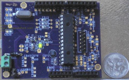
(flipped vertically) 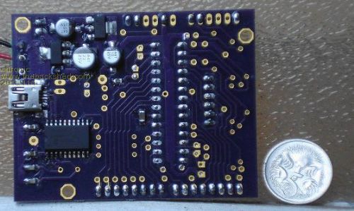
|
||||
| WhiteWizzard Guru Joined: 05/04/2013 Location: United KingdomPosts: 2983 |
Nice looking boards there; nice to see them all built up! I would have used ceramic caps instead of SMD electrolytics as I find the ceramics are cheaper, better spec, and smaller. The lower height off the ceramics may also make it easier to mount the PCB in an enclosure. NOT a criticism - just an observation 
Do let us know how they perform for your application(s) . . . . WW |
||||
| isochronic Guru Joined: 21/01/2012 Location: AustraliaPosts: 689 |
I certainly agree, the power supply would be better with solid caps.. the higher value ceramics are expensive here in aus still though. The boards are working well, either at 115k serial/usb with the interpreter or C, pickit3 and the ICSP pins etc. If someone wants to try micromite/MMBasic on it, send me details. I have updated and shared the project (gerbers), at https://www.oshpark.com/shared_projects/7wNYZfbj . In general I have found oshpark pretty good, excellent quality and a lot faster than usual. |
||||
Grogster Admin Group Joined: 31/12/2012 Location: New ZealandPosts: 9974 |
Yet another PCB for the MM family of chips. We are all spoilt for choice now.
Nice board. Purple soldermask is different.  Smoke makes things work. When the smoke gets out, it stops! |
||||
| isochronic Guru Joined: 21/01/2012 Location: AustraliaPosts: 689 |
A readme and component list : 2015-11-05_000614_mu2-bREADMEcomplist.zip and the lot 2015-11-05_000750_mu2b.zip |
||||
| isochronic Guru Joined: 21/01/2012 Location: AustraliaPosts: 689 |
To progress a little, I have tested the practicality of the board by running my solar position program in electride on it. I adjusted the solar position program (in electride) a bit so it ran in a loop, reading a gps module NMEA stream directly on a port B pin, and displayed the calculated solar elevation and azimuth results on a humble 16x2 lcd in a continuous update. This required setting up an auxiliary non-blocking read input, which is now woorking ok. Trials with a dummy gps text stream went ok. So I took the plunge and connected my gps module...and for seven glorious minutes, revelled in the sight of the sun position being updated every few seconds on the LCD. Nice !!! BUT... then the gps module expired. It is now apparently a short circuit between the 3.3v power and ground ... The pic port B pin is set solidly as an input, and not sending any current or voltage back to the gps... So - What would make a gps module burn out like that ???? Any suggestions ?? |
||||
| WhiteWizzard Guru Joined: 05/04/2013 Location: United KingdomPosts: 2983 |
Did you have any series resistors in the Tx and Rx lines? It is always worth adding these (I normally use either a 330R, 470R, or 1K) whenever connecting a module to a MicroMite. This will protect against 5v signals into a 3v3 pin (either way round), and also protect against shorts caused by an MM pin being at one logic level and the module pin being at the 'opposite' logic level (when both are outputs). I won't go on bout the 'quality' of 'cheap' units, but it could simply be a failure of the GPS module. Alternatively, it could be a 'coding' oversight that caused a 'short' on the GPS Tx pin (i.e. setting the MM Rx pin as an output and then with no resistor you have a potential short to the GPS output). The PICs are quite robust; even though spec'd at 15mA per I/O pin, I have passed a lot more through one (accidentally) and it survived ok. But the GPS may have very low current Maximum rating so a 'temporary short' would be enough to blow the module. This is unlikely as you state that all was working fine for seven minutes. Could there have been another 'condition' that occurred causing your program to jump somewhere else; if so then did the code generate a 'short' as outlined above? My money is on the GPS module. When buying these 'cheap' things from eBay I would recommend buying at east three. Expect at least one to fail, and hope that at least one works!!!
Do let us know if you track down the cause . . . . WW |
||||
| isochronic Guru Joined: 21/01/2012 Location: AustraliaPosts: 689 |
Thanks WW. ..I have looked into it a bit further. I think I may have (cough, splutter) stuffed up by using a metre-long cable to the gps so it could sit on a windowsill to get a clear signal...There is a fair bit of RF noise here which often causes cable problems. I used a typical 0.1 uf cap to decouple noise but the (now that I have read it ) gps spec suggests a fair bit more eg a ground plane, more ground connections, a ferrite filter , a 1uf cap and also a 0.1uf cap as well, ceramic of course. Until then I had not been using a cable, and everything was working ok. The two boards I used are ok with no ill effects and are stable. So I will progress with the idea that it was a noise/spike and I should have done it properly instead of trying to wing it 
|
||||
| WhiteWizzard Guru Joined: 05/04/2013 Location: United KingdomPosts: 2983 |
Glad your 'units' seemed to have survived the ordeal. 
So has your GPS module got a provision for plugging in an 'off-board' antenna? If so, then why not place the GPS module on the same PCB as the MM, and then have a 3m-5m patch antenna plugged into that. Allows you to then position the antenna near a window with no worries about noise 'polluting' lengthy Tx/Rx cables. If no patch antenna support, then why not consider this for a challenge! Connect the GPS module to a local MicroMite along with a RF module and housing in a small enclosure. Then providing you can power this near a window, you then have a RF enabled GPS module that can then communicate to your main MicroMite circuit located elsewhere (but obviously within RF range). This is something I have done to create a local TimeServer in the house to then supply accurate time to various MM's around the house. Great for my LED matrix clocks as only requires one GPS module to give total accuracy on all clocks & loggers! Alternatively, buy a GPS receiver with patch support
WW |
||||
| isochronic Guru Joined: 21/01/2012 Location: AustraliaPosts: 689 |
Yes an antenna would be the go. Good gps modules seem to be the expensive ones ! I am not using Micromite/MMBasic, just my own interpreter (electride)as yet. I may offer a built board without software for someone to try MM on it, I will look into that. That is a good idea, to use a RF module and a central reference. In the interim I have switched it over to use a 2ppm RTC, and it is chugging along printing the time and solar elevation and azimuth once a second. I expect that will need time resetting every month or so. I will switch in the little lcd display and wrap it up as a module. |
||||
| isochronic Guru Joined: 21/01/2012 Location: AustraliaPosts: 689 |
The board calculating solar position, using time from a ds3234 clock and preset latitude / longitude, updating once a second. 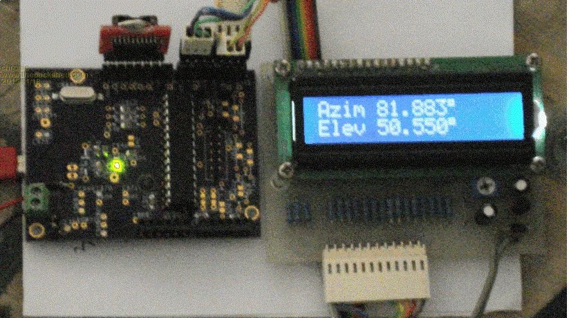
Now to try to drive two mirror motors..should be straightforward. On the other hand those 240x320 lcd's look so good... (apologies for the photo quality, a bit fuzzy this morning!) |
||||
| The Back Shed's forum code is written, and hosted, in Australia. | © JAQ Software 2026 |
