Notice. New forum software under development. It's going to miss a few functions and look a bit ugly for a while, but I'm working on it full time now as the old forum was too unstable. Couple days, all good. If you notice any issues, please contact me.
Herry Senior Member Joined: 31/05/2014 Location: AustraliaPosts: 261
Posted: 08:13am 21 Feb 2016
Copy link to clipboard
Print this post
Gulp! I am confused (not difficult). I assumed that the complete code was up to the test routine, and noticed that the data was never read. I then saw that after the test the code continued. I am assuming that the mm pins in use are 2,3,4,5,35,36,37,38 (8 of them) but how can that work if there are say 3 digits? And if the pins numbers are in the const seg block, what are 'drivepins (in this case 12,13,32,0)? How many pins are in fact used for this program (assume 3 digits)?Senior?! �Whatever it says, I'm a complete and utter beginner...
matherp Guru Joined: 11/12/2012 Location: United KingdomPosts: 11606
Posted: 08:39am 21 Feb 2016
Copy link to clipboard
Print this post
Don't be put off by the length of the code, most of it is just the data to display pseudo ascii characters.
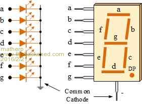
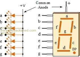
pins 2,3,4,5,35,36,37,38 connect to the LED segments which are usually labelled a to g (plus the decimal point dp if used). These connect internally on the display to that segment on all of the digits
pins 12,13,32,0 (only three specified as only three digits in use but you have to initialise all the array elements) connect to the common cathode or anode connections for each of the digits individually
In my example you will see I have set ndigits% to 3 i.e. a three digit display so I am using 8 + 3 pins to drive it. A four digit display would need 12 pins, a 2 digit 10. If you don't need a decimal point these numbers can be reduced by 1 but the code will need a bit of editing to avoid it trying to write to a non-existent pin.
I'm using a common anode display and driving the common pins using PNP transistors - bases connected to the micromite drive pins via resistors, emitters to 3.3V, collectors to the common anode pin for each of the digits.
To use a common cathode display you need to alter the relevant constants as per the comments.
const on%=0 'set to 1 if common cathode display
const off%=1 'set to 0 if common cathode display
const all_on%=0 'set to 255 if common cathode display
const all_off%=255 'set to 0 if common cathode display
The init_LED routine just reads in the segment data and sets up the pins and then critically starts up a timer which runs the routine "display" every 5 msecs.
Display is the key routine and is only comprised of 7 lines of executable code.
It displays the data on each digit in turn, so each 5msec just one of the digits is actually being illuminated. However, because of persistence of vision they all appear to be lit at once. For a three digit display it takes 15msec to complete the cycle of digits.
Within the "Display" routine the code knows which digit it is going to display next and which one it is displaying at the moment. It then gets the appropriate ascii character from the out$ string and using the digittosegment% array maps that onto the LED segments that should be lit for the relevant digit.
It then turns off the common drive to the previous digit, sets the individual segments required for the new digit and turns on its drive pin.
Finally, it updates the variable that stores which digit is being displayed and which digit to display next.
Edited by matherp 2016-02-22
Herry Senior Member Joined: 31/05/2014 Location: AustraliaPosts: 261
Posted: 10:16am 21 Feb 2016
Copy link to clipboard
Print this post
Thanks very much for that very lucid explanation. All I need to be clear abut now is taking out the test part, as it appears that half of the code is after the test. I already sussed that much of the code (particularly most of the matrix) can be ignored for my application, which is strictly digits 0-9 only and no dp. I see I was (accidentally?) on track with my thoughts that switching the cathodes for the digits was a much better way than eg 3 X 8 pins! BTW I assume you would use eg 557 for the transistors.Senior?! �Whatever it says, I'm a complete and utter beginner...
matherp Guru Joined: 11/12/2012 Location: United KingdomPosts: 11606
Posted: 11:31pm 21 Feb 2016
Copy link to clipboard
Print this post
Here is a version that strips out the dp and other ascii characters, except A-F so you can display hex if required
option explicit
option default none
'
' first define the display type and its connections, The pin connections must be in the order as commented
' The code assumes that for a common anode display the digit drives are connected via a PNP transistor
' The code assumes that for a common cathode display the digit drives are connected via a NPN transistor
' The segment connections can be made directly to the Micromite pins but adding a current limiting resistor is best practice
'
const ndigits%=3 'set the number of digits in the display
const on%=0 'set to 1 if common cathode display
const off%=1 'set to 0 if common cathode display
const all_on%=0 'set to 255 if common cathode display
const all_off%=255 'set to 0 if common cathode display
'
' pin assignments
'
const seg_a%=2 'top
const seg_b%=3 'upper right
const seg_c%=4 'lower right
const seg_d%=5 'bottom
const seg_e%=35 'lower left
const seg_f%=36 'upper left
const seg_g%=37 'centre
dim drivepins%(3)=(12,13,32,0)'left, midleft, midright,right
'
dim dpos%=0, lastpos%=0, out$ length ndigits%
dim digittosegment%(15) ' array to hold the character bitmaps
'
' set the bit patterns for all "displayable" HEX characters
'
DATA &B1111110 ' 0
DATA &B0110000 ' 1
DATA &B1101101 ' 2
DATA &B1111001 ' 3
DATA &B0110011 ' 4
DATA &B1011011 ' 5
DATA &B1011111 ' 6
DATA &B1110000 ' 7
DATA &B1111111 ' 8
DATA &B1111011 ' 9
DATA &B1110111 ' 10 "A"
DATA &B0011111 ' 11 "B"
DATA &B1001110 ' 12 "C"
DATA &B0111101 ' 13 "D"
DATA &B1001111 ' 14 "E"
DATA &B1000111 ' 15 "F"
'
'*************************************************************************************
'
' Test program
'
dim i%=0
out$=str$(i%,ndigits%)
init_LED
out$=("ABC")
pause 2000
out$=("DEF")
pause 2000
do 'count continuously without overflowing
pause 250
out$=str$(i%,ndigits%)
i%=i%+1
if i%>=10^ndigits% then i%=0
loop
'
'*************************************************************************************
'
' initialisation and display subroutines
'
sub display 'called by the timer interrupt, cycles through the digits, outputs the contents of the out$ string
local integer i,k
i=asc(mid$(out$,dpos%+1,1)) 'get the ascii character
if i<48 or i> 71 or (i > 57 and i < 65) then 'test for a number or a hex letter
k=all_off% 'if not switch all off
else 'convert the ascii into an index into the segment array
i=i-48
if i> 9 then i=i-7
k=digittosegment%(i)
endif
pin(drivepins%(lastpos%))=off% 'turn off the drivepins% to the last digit
port(seg_g%,1,seg_f%,1,seg_e%,1,seg_d%,1,seg_c%,1,seg_b%,1,seg_a%,1)=k 'set the new segment map
pin(drivepins%(dpos%))=on% 'turn on the drivepins% to the new digit
lastpos%=dpos%
dpos% =(dpos%+1) mod ndigits%
end sub
'
sub init_LED
' load the arrays of pin numbers and set all the pins to the "off" position
' this will be 1 for common anode and 0 for common cathode
local i%
out$=space$(ndigits%) 'initialise the display to blank
for i%= 0 to 15 'read in the character bitmaps
read digittosegment%(i%)
next i%
if off% then 'for common anode bits will be set to 0 to turn on so invert the character map
for i%=0 to 15
digittosegment%(i%)=digittosegment%(i%) XOR &HFF
next i%
endif
Just a quick note to this thread that helped me get my multiplexed 7 Segment LED's working.
I am using 2.3" large LEDs * 4 for a clock project.
I was looking at the examples in this thread on how to hook everything up and it wasn't really working properly until it occurred to me that the examples in this thread are for the smaller single led per segment displays.
My displays have 3 LED's per segment so of course were going to draw a lot more current and had a large forward voltage which required 12v to drive them.
In the end I used ULN2803/UDN2981 chips to switch the 12v required to drive the LEDs.
My main point here is if using larger LED displays don't hook them up directly to the Pic!
I've also decided to wire each segment I need on each of the four displays to an individual pin (total 23 pins) so I don't have to multiplex.
Lastly, not sure if I'm the only person in the world that thinks having a bright clock in the bedroom when trying to sleep is a problem but everyone I ask reckons it's no big deal. I have gone through several clocks trying to find one that will go really dim at night but be readable during the day and haven't had much luck.
So my design is going to use an LDR/photodiode/phototransistor to dim the display right down at night so I can sleep :)