
|
|
Forum Index : Microcontroller and PC projects : Micromite low power battery monitor
| Author | Message | ||||
OA47 Guru Joined: 11/04/2012 Location: AustraliaPosts: 1050 |
As I have about 10 vehicles with a lead acid 12 volt battery and some of them are used infrequently, I wanted a simple way of monitoring the battery at a glance to be warned when they needed a charge. I thought of analogue meters and LCD/LED readouts but they are limited with costs, battery drain and the need for close up inspection. Given the Micromite can be set in a very low power mode I investigated a simple method of reading the battery voltage and flashing an LED for a short duration to indicate the voltage. I settled with a red/green/amber high efficiency LED that can be pulsed for 2mS and give a good amount of light to be noticed over a few meters distance. I chose to flash green if the terminal voltage was above 12.5 volts and red below 12 volts with the area between a graduated orange (from more green to more red). The circuit will draw less than 100uA per if averaged over time (even though the LED is operated at over 20mA it is only for a very minimal time). The current draw is minimised by using a low quiescent current 3 terminal regulator. Only a handful of components are needed to complete the circuit and I managed to simply encapsulate the unit in a short piece of 18mm conduit to protect and insulate the unit. I found a 2 milliseconds flash from the LEDs that I used was adequate but the length of the flash may be altered dependant on the power of the LED. 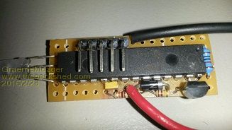
Here is the code I have used. '************************************************************* '* THIS PROGRAM WILL MONITOR THE STATE OF A 12 VOLT BATTERY * '* AND FLASH A TRI COLOR LED.GREEN For >12.5V, AMBER BETWEEN * '* 12 And 12.5 V And RED BELOW 12V. * '* USING THE MCP1703 REGULATOR CURRENT DRAW IS MICROAMPS/HR * '* * '* MMBASIC 5.1 For MICROMITE II WITH OPTION AUTORUN ON * '* * '* THANKS TO GEOFF GRAHAM FOR ALL OF HIS WORK FEB 2016 * '************************************************************* Option EXPLICIT Dim BLNK,CAL,VOLTS,URG SetPin 14,DOUT 'RED LED ANODE SetPin 15,DOUT 'GREEN LED ANODE SetPin 23,AIN '10K/100K RESISTOR DIVIDER BLNK=2 'LED PULSE LENGTH IN MILLISECONDS CAL=11.26 'ANALOG CALIBRATION START: PAUSE BLNK+1 'WAIT FOR LED ACTIVITY TO CEASE BEFORE SLEEP CPU SLEEP 3 'PUT UNIT TO SLEEP FOR APPROX 3 SECONDS VOLTS=0.6+Pin(23)*CAL 'CALIBRATED FOR RESISTOR DIVIDER & PROTECTION DIODE URG=1+(VOLTS-12)*2 'URG MANAGES THE AMOUNT OF RED/GREEN MIX Print VOLTS 'USED TO CALIBRATE DIVIDER If VOLTS > 12.5 Then Pulse 15,BLNK 'FLASH GREEN If VOLTS > 12 And VOLTS < 12.5 Then 'FLASH AMBER Pulse 15,BLNK Pulse 14,BLNK/URG End If If VOLTS < 12 Then Pulse 14,BLNK 'FLASH RED GoTo START 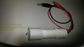
Thankyou to the Backshedders that assisted in earlier posts. GM |
||||
| viscomjim Guru Joined: 08/01/2014 Location: United StatesPosts: 925 |
What an excellent project. Great work Graeme! I love the enclosure too. Have to keep that one in mind. |
||||
| OA47 Guru Joined: 11/04/2012 Location: AustraliaPosts: 1050 |
Thanks Jim |
||||
TassyJim Guru Joined: 07/08/2011 Location: AustraliaPosts: 6543 |
Simple and effective. I might add this to my solar powered gate. It will save a wireless link back to the house. Jim VK7JH MMedit |
||||
| OA47 Guru Joined: 11/04/2012 Location: AustraliaPosts: 1050 |
Not a problem Jim. Thank you again for your contribution.  |
||||
| paceman Guru Joined: 07/10/2011 Location: AustraliaPosts: 1329 |
Nice job Graeme - as Jim said, simple and effective. It's very compact too and the code couldn't be more succinct. Greg |
||||
disco4now Guru Joined: 18/12/2014 Location: AustraliaPosts: 1130 |
Pretty clever using pins 14 and 15 so the led is right next to the pins at the end. A neat little project. It probably would not make a lot of difference as its asleep most of the time, but you could consider running the CPU at 5MHz to save a bit more power. Regards Gerry F4 H7FotSF4xGT |
||||
| OA47 Guru Joined: 11/04/2012 Location: AustraliaPosts: 1050 |
Gerry I did try running the CPU @ 5Mhz but I couldn't see any measurable difference. I left it at full speed as I thought that it would pulse both LEDs virtually simultaneously to get the amber colours, even though there are two commands: Pulse 15,BLNK Pulse 14,BLNK/URG Thanks for your comments. GM |
||||
drkl Senior Member Joined: 18/10/2015 Location: HungaryPosts: 102 |
Hi, The basic idea is rethinking: 10 Status Indication. 'ANALOG MEASURMENT TO RGB LEDS 'THREE COLORS THREE STATES (SLOW-FLASH=FAST-FLASH=FULL-LIGHT) 'THE SCALE: SS,RS-RF-RL-BS-BF-BL-GS-GF-GL 'SS-BELOW XMIN 'DRK 2016.02.29 'V1.0 '======[ INITIALISATIONS ]============================================ OPTION EXPLICIT 'LEDEK: CONST LEDR=2,LEDG=3,LEDB=4 SETPIN LEDR,DOUT:SETPIN LEDG,DOUT:SETPIN LEDB,DOUT 'ANALOG: CONST AN2=22:SETPIN AN2,AIN 'HERE ANA>0...3.2 GENERAL: XMIN...XMAX DIM K$,U,I,J,ALAK$(10) 'LEDLIGHTS DATA "SS","RS","RF","RL","BS","BF","BL","GS","GF","GL" FOR I = 0 TO 9: READ ALAK$(I): NEXT I 'FELTOLTES CONST XMIN=0,XMAX=3.2 '10 STATES BETWEEN XMIN-XMAX BORDERS '======[ PROGRAM ]===================================================== DO FOR J=1 TO 20 U=PIN(AN2) ' I=INT((U/3.3)*9+1) IF U<XMIN THEN U=XMIN IF U>XMAX THEN U=XMAX I=INT(((U-XMIN)/(XMAX-XMIN))*9) ' ? I," ",U LEDLGHT ALAK$(I) NEXT J LEDSOFF PAUSE 10 ' CPU SLEEP 3 LOOP '======[ SUBROUTINES, FUNCTIONS ]====================================== 'GIVEN COLOUR GIVEN SPEED SUB LEDLGHT COSP$ LOCAL COL$,SPEED$ COL$=LEFT$(COSP$,1):SPEED$=RIGHT$(COSP$,1) IF COSP$="SS" THEN LEDSOFF EXIT SUB ENDIF IF COL$="R" THEN IF SPEED$="S" THEN LEDSLOW LEDR IF SPEED$="F" THEN LEDFAST LEDR IF SPEED$="L" THEN LEDCONT LEDR ENDIF IF COL$="B" THEN IF SPEED$="S" THEN LEDSLOW LEDB IF SPEED$="F" THEN LEDFAST LEDB IF SPEED$="L" THEN LEDCONT LEDB ENDIF IF COL$="G" THEN IF SPEED$="S" THEN LEDSLOW LEDG IF SPEED$="F" THEN LEDFAST LEDG IF SPEED$="L" THEN LEDCONT LEDG ENDIF END SUB ' SUB LEDSLOW PN LEDSOFF PIN(PN)=1 PAUSE 5 PIN(PN)=0 PAUSE 85 END SUB ' SUB LEDFAST PN LEDSOFF PIN(PN)=1 PAUSE 30 PIN(PN)=0 PAUSE 60 END SUB ' SUB LEDCONT PN LEDSOFF PIN(PN)=1 PAUSE 100 END SUB ' SUB LEDSOFF PIN(LEDR)=0 PIN(LEDB)=0 PIN(LEDG)=0 END SUB ' END '**[ PROGRAM ENDS ]************************************************ drkl |
||||
| OA47 Guru Joined: 11/04/2012 Location: AustraliaPosts: 1050 |
What is the consensus of opinion regarding what to do with the unused pins of the MM given the need for minimal power consumption? GM |
||||
| JohnS Guru Joined: 18/11/2011 Location: United KingdomPosts: 4344 |
I think the PIC32 docs discuss it. You either set them as outputs low or inputs with a pullup. (You really need to avoid them floating.) As there are some issues with the internal pullups (details escape me) I suppose you'd need external resistors. I don't know what the biggest safe pullup is. 10K or more I guess. See what others say as I'm not by a long way the best on this! John |
||||
| WhiteWizzard Guru Joined: 05/04/2013 Location: United KingdomPosts: 2991 |
Out of interest, what 'technical' state are they in if set to 'OFF' in MMBasic? |
||||
| Benzol Regular Member Joined: 07/01/2015 Location: AustraliaPosts: 64 |
Hi OA47 please excuse my ignorance but I'm having a bit of trouble understanding the code above. CAL=11.26 'ANALOG CALIBRATION START: PAUSE BLNK+1 'WAIT FOR LED ACTIVITY TO CEASE BEFORE SLEEP CPU SLEEP 3 'PUT UNIT TO SLEEP FOR APPROX 3 SECONDS VOLTS=0.6+Pin(23)*CAL 'CALIBRATED FOR RESISTOR DIVIDER & PROTECTION DIODE Can you explain how the calibrate value of 11.26 is derived and also the volts calculation of 0.6+Pin(23)*cal? I figured with the 10k / 100k voltage divider and i/p voltage of 12v would give a voltage of 1.036 volts at pin 23 but I'm a bit lost from there. regards db |
||||
| OA47 Guru Joined: 11/04/2012 Location: AustraliaPosts: 1050 |
Benzol In a perfect world, the voltage divider should be a factor of 11 but due to tolerances in the resistors and the load of the pic chip when I measured the actual voltage it was a factor of 11.26. I used a 1N4001 protection diode on the positive lead of the unit. This means that the voltage measured will be reduced by the forward voltage of the diode and must be added to the voltage measured by the PIC. In this case the forward voltage of the diode is 0.6 volts. The LED will be on for the time period of BLNK (a couple of milliseconds) If the PIC goes to sleep before the LED has finished its pulse then the LED will continue to draw power while the PIC is asleep. Hope this makes sense GM |
||||
| Benzol Regular Member Joined: 07/01/2015 Location: AustraliaPosts: 64 |
Thanks Graeme. It took me while and lots of hair pulling and banging the calculator but once it clicked I realised how clever that approach was. Thank you for the help. Do you mind if I use it for my own 12 system monitor? regards db |
||||
| aargee Senior Member Joined: 21/08/2008 Location: AustraliaPosts: 255 |
Overkill for a Micromite? So what's the difference to this:
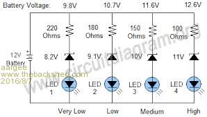
Your design may be a bit more precise, but at the fluctuating temperatures in a car's engine bay, all I can get is an indication at best for state of charge.  For crying out loud, all I wanted to do was flash this blasted LED. |
||||
redrok Senior Member Joined: 15/09/2014 Location: United StatesPosts: 209 |
Hi GMThis is not a question specific to a micros. This is mostly a general problem with ALL CMOS digital device input pins. Since the input impedance is very high, often greater than 100MOhms, stray leakage currents or static charges can leave the pin at a mid voltage between a logic Hi or Low. Somewhere in this no mans land pairs of P and N channel FETs start to conduct current between the power rails. Not much but it isn't 0. Technically this occurs with every logic transition but the time in the Regine is so short the power dissipation is negligible. Anyway, the rule is to make all unused INPUT pins be either at a logic Hi or Low level, NO EXCEPTIONS. The best way is with pull up or pull down resistors. Generally you only need 1 resistor and connect all pins to it. In most cases you don't even need the resistor. I generally tie them directly to ground. Since we are talking about a micro, we don't need to do any connecting at all. Simply configure the unused pins as digital outputs and set to low. Do this once at startup. Setting the pin to a digital output low essentially draws no current. BTW resistors are required when driving high impedance loads such as MOSFET and such so they are in a predetermined state, usually off, when the driving micro is not running. redrok |
||||
| mikeb Senior Member Joined: 10/04/2016 Location: AustraliaPosts: 180 |
When the pin is 'unconfigured' it is deemed to be an input. All pins on the PIC32 have schmitt trigger circuitry enabled, on the silicon, when configured as a digital input. By default, any input associated with the A to D converter module will be in an analogue input mode after reset\power up. The long and the short of it all is that 'pullup's\pulldowns are unnecessary, as far as the PIC32 is concerned. Some 'electrically noisy' environments may benefit from pullup's\pulldowns but they will be the exception. Your only concern will be for external logic, which may need a defined state, until the PIC32 is able to take control of the pins which need to be outputs, following a reset or power up. The datasheet is your friend. There are 10 kinds of people in the world. Those that understand binary and those that don't. |
||||
| The Back Shed's forum code is written, and hosted, in Australia. | © JAQ Software 2026 |
