
|
|
Forum Index : Microcontroller and PC projects : Convert 24V ac to 24V DC
| Author | Message | ||||
| MM_Wombat Senior Member Joined: 12/12/2011 Location: AustraliaPosts: 139 |
Hi all, What would be the best way to convert 24 V AC to 24 V DC to run some 24V led's from an existing 24V ac supply. The existing supply powers some pumps, and the led's are needed for illumination of the product. Regards MM_Wombat Keep plugging away, it is fun learning But can be expensive (if you keep blowing things up). Maximite, ColourMaximite, MM+ |
||||
| Gizmo Admin Group Joined: 05/06/2004 Location: AustraliaPosts: 5185 |
How sensitive are your LED's to higher voltage. If you feed 24VAC into a bridge rectifier, you end up with about 33VDC. If your LED's wont tolerate 33VDC, then how many amps are we talking about. Regulating 33VDC down to 24VDC is easy or hard, depending on the current needed to run the LED's Glenn The best time to plant a tree was twenty years ago, the second best time is right now. JAQ |
||||
| hitsware Guru Joined: 23/11/2012 Location: United StatesPosts: 535 |
24 volt LEDs ? Most LEDs are around 1 to 3 volts forward voltage. 24 volt reverse ? They will run on AC ... Try simply resistors to the LEDs. Start with large values and adjust down ..... |
||||
Grogster Admin Group Joined: 31/12/2012 Location: New ZealandPosts: 9984 |
hitsware - he will be using one of those strings of LED's and those you just feed in the juice, as each LED has it's own dropper resistor normally. That's my guess as to what he has, anyway. Smoke makes things work. When the smoke gets out, it stops! |
||||
| hitsware Guru Joined: 23/11/2012 Location: United StatesPosts: 535 |
Ahh ............Then: Adjust R for 24vdc across led 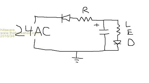
BUT reverse diode !!!! ...duh |
||||
palcal Guru Joined: 12/10/2011 Location: AustraliaPosts: 2039 |
You don't need the diode the LED is a diode. Paul Edit. To run one LED from 24 Volts R=1200 ohms. so the LED with 1200R in series and connect to 24 AC or DC "It is better to be ignorant and ask a stupid question than to be plain Stupid and not ask at all" |
||||
| 5bar Newbie Joined: 10/07/2014 Location: AustraliaPosts: 16 |
I strongly suggest you keep the diode reverse voltage of LEDs is not good cheers, Lin I can count to 31 on one hand |
||||
| palcal Guru Joined: 12/10/2011 Location: AustraliaPosts: 2039 |
Yes I seem to remember something about that. Paul "It is better to be ignorant and ask a stupid question than to be plain Stupid and not ask at all" |
||||
| hitsware Guru Joined: 23/11/2012 Location: United StatesPosts: 535 |
You don't need the cap either, but might get flicker without it .... |
||||
bigmik Guru Joined: 20/06/2011 Location: AustraliaPosts: 2981 |
Hi Hitsware, All, The halfwave rectification you show would result in only 16.97Vdc or 14.55Vdc.. (why the different values???) I cant remember now if halfwave gives the RMS figure (0.7071) or the Average (0.6063) when converting to DC (I seem to remember it was the average so you would only get 14.55Vdc..) In either case you need a full wave rectification (gives 33.94Vdc ... with 1.4142 RMS figure)) and a dropping resistor (of sufficient wattage) or a 24 V Reg but I would go for the dropping resistor if the LEDs were to be set to one brightness only.. Filter cap of 1000v and a couple of 100nf caps if flicker is evident and not wanted.. Regards, Mick Mick's uMite Stuff can be found >>> HERE (Kindly hosted by Dontronics) <<< |
||||
| MM_Wombat Senior Member Joined: 12/12/2011 Location: AustraliaPosts: 139 |
Hi all, Thanks for all the info. The project is a drink dispenser, like at a fast food restaurant, that needed to be lit. Another company makes the dispenser and are already using a 24V AC PSU for the pumps. My company is printing the fascia's and lighting the device. My boss had already ordered the 24V DC leds strips, which have to be IP rated (liquid resist). I found this circuit on DiscoverCircuits.com and will probably use this as it outputs close to 24V DC consistently, or so the author describes, to a max of 2 amps. His description was pretty much what is required. 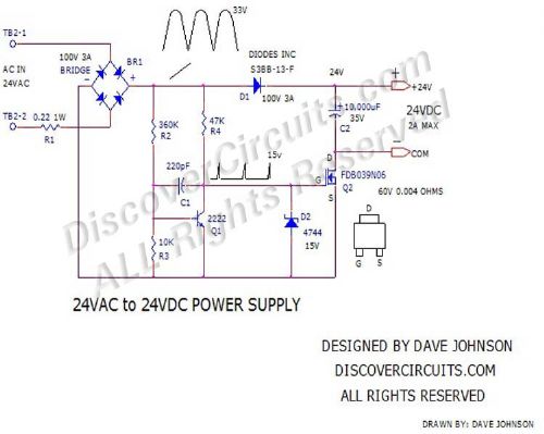
Thanks again to all MM_Wombat Keep plugging away, it is fun learning But can be expensive (if you keep blowing things up). Maximite, ColourMaximite, MM+ |
||||
| HankR Senior Member Joined: 02/01/2015 Location: United StatesPosts: 209 |
Whether half wave or full wave rectification is employed, with enough capacitance the circuit will reach the peak voltage of the 24 volts RMS transformer which is about 34 volts. The only difference is that full wave will get to the peak with less capacitance (and the ripple frequency will be doubled of course). Increased loading (if the cap isn't big enough) will result in progressively lower output voltage below the peak value. The diode (in the hand drawn circuit employing 1/2 wave rectification) is desirable not just for the sake of the LED, but to prevent "power level" reverse polarity voltage getting to the single polarized filter cap. Applying a reverse polarity voltage (unless it's just a current-limited, low level signal) to any type of polarized cap I can think of results in bad things happening pretty quickly, esp. with tantalums which often explode in those circumstances. Another thing is that without the diode there would not be a steady 34 volts at the output. It would still reach 34 volts at the top of the AC sine wave excursion, but only for an instant. Hank |
||||
| 5bar Newbie Joined: 10/07/2014 Location: AustraliaPosts: 16 |
Don't get bogged down here LEDs are more about current than voltage RMS, .707 x peak will give you equivalent DC POWER If you want to keep it simple, I suggest a bridge rectifier with a chunky smoothing cap, 1000uF + Followed by LM 350 reg with appropriate resistors to set voltage Cheers, Lin I can count to 31 on one hand |
||||
| hitsware Guru Joined: 23/11/2012 Location: United StatesPosts: 535 |
Duh .......... Looks like only diode and capacitor needed. Perhaps ~ < 24V , but should work ..... 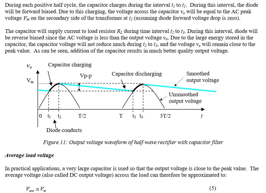
|
||||
| HankR Senior Member Joined: 02/01/2015 Location: United StatesPosts: 209 |
Hitsware, Your graph and accompanying text amplifies on what I stated before. With adequate capacitance the filtered DC output (Vm) will be about 34 volts with varying degrees of ripple. There are also design charts available that show that amount of ripple specifically (normalized values) for different loadings. Even with just raw full-wave rectified DC (no filtering at all), the voltage will be *above 24 volts* half the time, maxing out at 34 volts at the peaks. So it's hard to not get 24 volts or above from a 24 volt RMS AC source. With adequately filtered DC, it all the time above 24 volts; with raw full-wave unfiltered DC it's above 24 volts half the time. In your diagram resistance R should be removed because it could interfere with the quick charging of the cap to peak voltage (a small resistance R could be retained to limit inrush current when the power supply is switched on). The un-named resistor will serve to limit LED current. MM_W, could you tell us how much total current the LEDs use? I see where you might have already settled on a circuit, but this will be instructive. Hank |
||||
| hitsware Guru Joined: 23/11/2012 Location: United StatesPosts: 535 |
Capacitors are our friends .....  |
||||
| MM_Wombat Senior Member Joined: 12/12/2011 Location: AustraliaPosts: 139 |
@HankR The boss wasn't in today, but I will ask him for some more info.. MM_Wombat Keep plugging away, it is fun learning But can be expensive (if you keep blowing things up). Maximite, ColourMaximite, MM+ |
||||
| HankR Senior Member Joined: 02/01/2015 Location: United StatesPosts: 209 |
Okay, just an approximate figure is fine. I might give the capacitor values for a few current drains anyway just for general power supply design purposes. |
||||
| The Back Shed's forum code is written, and hosted, in Australia. | © JAQ Software 2026 |
