
|
|
Forum Index : Microcontroller and PC projects : USB/Serial 4 digit 7 Segment module
| Author | Message | ||||
| MicroBlocks Guru Joined: 12/05/2012 Location: ThailandPosts: 2209 |
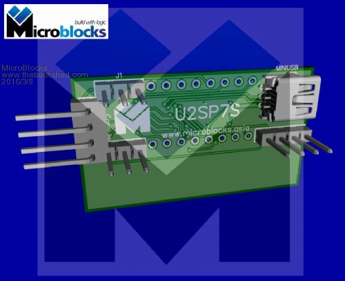
I designed a little PCB that can hold a 4 digit 7 segment display. While i was doing that i realized i had some pins left and used them to add USB to Serial and some switches. I would like to keep my 'MicroBlocks' compact and easy to use, but also versatile. Sometimes however i go a bit too far and i was wondering what you guys are thinking. Should i keep the switches or make the board smaller by dropping them? Size of the pcb is 42x14mm without keys and 42x24mm with the keys. I have not written the software yet. Idea is to use it as a standard USB-Serial converter and capture special characters coming in over the RX line (from the mcu). 0x00 - 0x0F would then be display as '0'-'9' and 'A'-'F', 0x10 followed by five values to set any combination of segments. The software will then build a little table in memory with all the right segments on and then loop very rapidly and display digit by digit. It will then also scan the keys and output them over the TX line (to the mcu, just as characters from a terminal). I think '1' - '5' would be the easiest to use. You can then decide in your own software what to do with those keys. When using only with the USB you could use it to for instance show the CPU temperature, or other info from your system. Or even how many emails are in your inbox. As it is a virtual comport anything that you would like can be displayed by making a little program that send data over USB. Schematic: 2016-03-08_201353_DipTrace_Schematic_-_U2SP7S.pdf PCB: 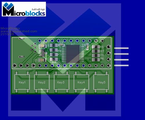
The display that mounts on top: 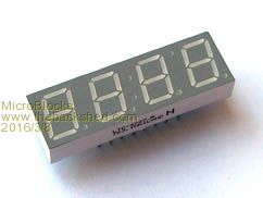
Microblocks. Build with logic. |
||||
| HankR Senior Member Joined: 02/01/2015 Location: United StatesPosts: 209 |
Of course the best is always make both versions, but for me this is a pretty easy decision on how to vote. I'd prefer a smaller board (thus lower product cost I hope), but do include some pads for the switches. Often a designer might need the switches off-board; in fact, that is probably the vast majority of cases. |
||||
| HankR Senior Member Joined: 02/01/2015 Location: United StatesPosts: 209 |
If all five can't fit, even two or three would be useful. |
||||
| MicroBlocks Guru Joined: 12/05/2012 Location: ThailandPosts: 2209 |
I agree with your points. I never have switches directly on the pcb, so that is another point in favor of just providing the connections. I changed it accordingly and also moved the parts to the bottom of the pcb so that any heat can dissipated more easy and is not trapped between the LED and the PCB. Also if something breaks it is easier to do a repair as all the parts are reachable. 2016-03-09_123239_DipTrace_Schematic_-_U2SP7S.pdf Front: 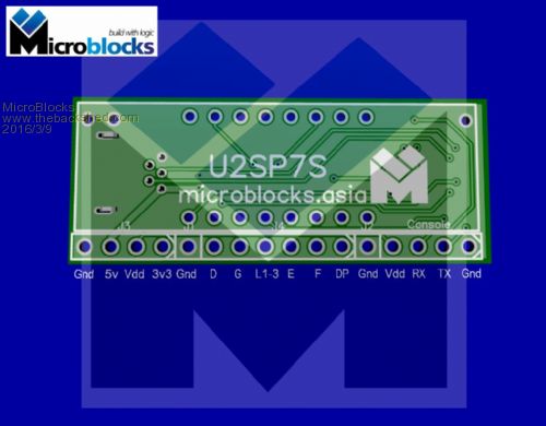
Back: 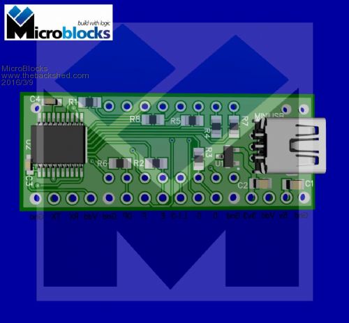
Microblocks. Build with logic. |
||||
| The Back Shed's forum code is written, and hosted, in Australia. | © JAQ Software 2026 |
