
|
|
Forum Index : Microcontroller and PC projects : Curses.......
| Author | Message | ||||
Grogster Admin Group Joined: 31/12/2012 Location: New ZealandPosts: 9984 |
I put the supply rail onto the module in reverse polarity to what it should have been.  A very silly schoolboy mistake on my part. A very silly schoolboy mistake on my part. 
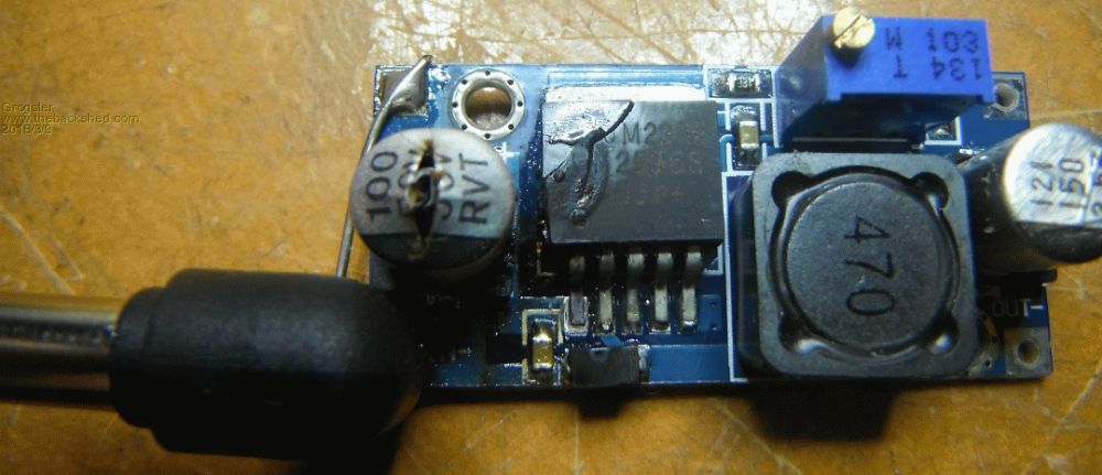
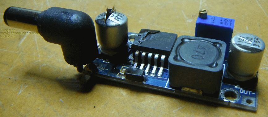
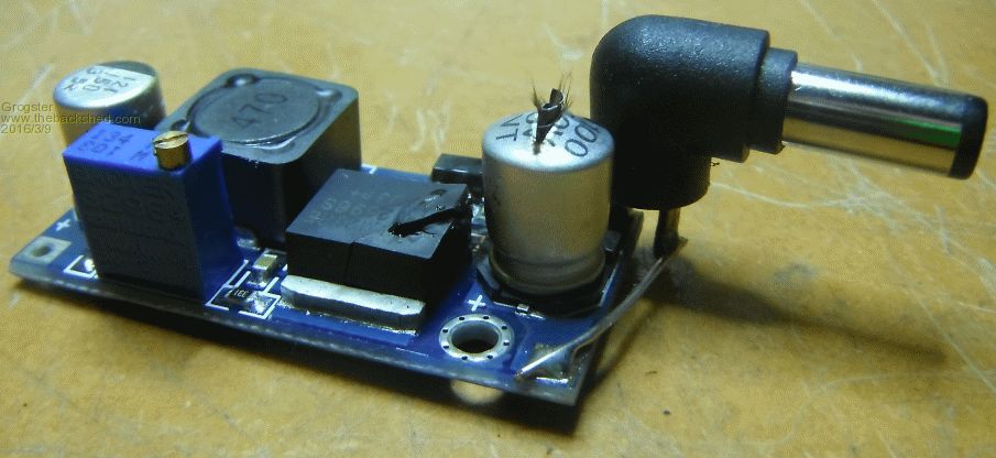
This was an impressive failure. The electro on the input turned into a firework, and the regulator glowed deep orange through the crack in it's case. A surprising amount of smoke came from the electro. I instantly knew something was very badly wrong at the first 'Crack!' noise, but by the time I had pulled the power, it was all over..... 36v @ up to 11A rail, so cooking this module was nothing to the PSU. Initial testing following removal of the cooked module reveals no damage, which is lucky. The module was not connected to anything, only the input voltage. Other devices on the same supply don't appear to have suffered for this current surge - lucky me. Oh well - onwards and upwards....... EDIT: Just found that the relay that controls the main supply rail is now welded closed. 
Therefore, a little bit of damage, so I will have to extract that power relay and replace it. I hate to think the current that could have been flowing into that fault, but I expect it could have been the current limit of the PSU(11A or so), and that has obviously cooked the relay N.O. contacts!  Smoke makes things work. When the smoke gets out, it stops! |
||||
| HankR Senior Member Joined: 02/01/2015 Location: United StatesPosts: 209 |
Grogster, You know how I like working with you on your excellent preamp project, so I say this as a friend. You **must** start using a current limited supply for your development work! And it must be set to a realistic low value when working on these low power devices. If you do not have such a supply get one. If you can't afford one, we will raise the money and buy one for you. :) I think your main schoolboy mistake is using an inappropriately sized supply (capable of 5 to 10 times too much current) for development work and testing. Even using a simple series resistor between that oaf of a PS and your device under test would have prevented this kind of catastrophic damage. Not to mention a simple series pigtail lead inline fast-blow fuse of the proper low value (an amp or less maybe?). Then the warning that something was wrong would not have been a snap, or pop, or poof of smoke, but a steep drop in the delivered voltage to the DUT because of a large voltage drop across the series resistor. No harm done to anything. Or with the use of a fuse, just an immediately blown fuse. Not sure if it was on the Back Shed or in offlist email, but hasn't this scenario happened to you before in the past year? Hank |
||||
| Grogster Admin Group Joined: 31/12/2012 Location: New ZealandPosts: 9984 |
Hank - The PSU is the main supply for the audio amplifier project - it has to have that grunt, to power the amplifier module. I was tapping off the main amplifier rail at the amplifier. The 36v is current limited by the PSU - but at 11A or so - the capacity of the supply itself. 
I have all the bits to build a current-adjustable buck/boost PSU unit, I just have not got around to building the thing yet. That would not have saved me in this situation even if I DID have it, cos I would still have been using the grunty amplifier PSU. I've found out something else since that opps above, and that is that the inrush current to the amp board is substantial. It welds the relay closed as soon as you power up. Bypassing the relay, and connecting via a multimeter, when you touch the power lead to the amp input firmly, you get a large blue spark, and the multimeter lead even spot-welds itself to the power input terminal. Once running, current of the amp is 200mA. There is 11x 220uF low-esr filter caps on the input. I am guessing this is what is causing the inrush current. While I have your ear, any suggestions on ways around that? Bearing in mind that I still need to be able to pass the large current when the amp is actually running, so I need a way to stop ONLY the inrush current. Perhaps a small-value 10W wire-wound resistor or something like that do you think? Smoke makes things work. When the smoke gets out, it stops! |
||||
| HankR Senior Member Joined: 02/01/2015 Location: United StatesPosts: 209 |
Grogs, One sort of basic, somewhat old-fashioned way would be to use that kind of series resistor you mentioned, but have it shunted out by a relay that activates after a delay of a few seconds. Since the capacitors have charged gradually to full voltage by the time the relay shunts, the relay contacts can be fairly light duty, and there is no danger of their getting welded. The delay circuit can be primitive, perhaps consisting only of an fet and R-C circuit. This kind of anti-surge circuit is used in big, hefty studio photo strobe lamp supplies where the voltages are up in the many hundreds of volts and applied directly to banks of large capacitors. This is a method that first comes to mind and I think might be the best. As always, there are other approaches available. Hank |
||||
| Grogster Admin Group Joined: 31/12/2012 Location: New ZealandPosts: 9984 |
Nice idea!!! 
The power relay is already switched from the main controller board(as you know), so I can keep this relay as-is, and add another one - I have spare I/O pins so I can assign one of the spares to the extra relay and use that to shunt the resistor. I will hook this up on the bench tomorrow and try it out. Do you have a recommended resistor value? I have some 1R 10W wire-wound ones, and various low-value 5W ones. Smoke makes things work. When the smoke gets out, it stops! |
||||
| HankR Senior Member Joined: 02/01/2015 Location: United StatesPosts: 209 |
Something in the area of 180 to 360 ohms. Incidentally, this is also roughly the size of the series resistor you could have had in series with that little module to keep it from detonating. That 36 volt PS line should be fused. Also each speaker lead should be fused. Forgot to mention that much earlier. |
||||
| Grogster Admin Group Joined: 31/12/2012 Location: New ZealandPosts: 9984 |
Acknowledged. I can add the fuses - I will shoe-horn in a fuse-box to cover all those bases - good ideas. Simple fuses could be speaker-savers if something goes wrong. There are also PTC's or Polyswitch protector things - do you have any opinion of those when used for speaker protection? Smoke makes things work. When the smoke gets out, it stops! |
||||
boss Senior Member Joined: 19/08/2011 Location: CanadaPosts: 268 |
@Grogster I sent one Snadpic board to the "Silicon Heaven" same way (blown solid capacitor). Since this experience all my PSU are home made, transformer based and contain over-voltage protection (resettable fuse and power transistor) circuit. Bo |
||||
palcal Guru Joined: 12/10/2011 Location: AustraliaPosts: 2039 |
Probably not suitable in this situation but many years ago I built a model train controller and to prevent damage from a short across the tracks it used a 12v. car headlamp bulb in series with the supply. With not much current flowing the bulb did not light and so had a low resistance but when a short occurred the bulb would light fully and the increased resistance of the bulb protected the circuit. Paul. "It is better to be ignorant and ask a stupid question than to be plain Stupid and not ask at all" |
||||
| HankR Senior Member Joined: 02/01/2015 Location: United StatesPosts: 209 |
The short answer is not suitable for primary protection that should be located in your amp enclosure. Some speaker companies incorporate these Polyswitch type devices right in their speakers, esp. tweeters, but that is only as backup to protection that should be in the power amplifier; and in the amp it should be a faster acting type system, such as electronic circuit based, or just plain fast-fusing. |
||||
| Grogster Admin Group Joined: 31/12/2012 Location: New ZealandPosts: 9984 |
Acknowledged and understood. Fuses it is then. Smoke makes things work. When the smoke gets out, it stops! |
||||
| Grogster Admin Group Joined: 31/12/2012 Location: New ZealandPosts: 9984 |
I plan to use a 50R 50W high-power resistor for the series in-rush current limit, which is then bypassed by a relay after a couple of seconds at power-up. 50W resistors According to Ohm's law, and assuming that the input filter caps on the amp board are effectively equivalent to a short-circuit to ground at the instant you apply power, with them rapidly charging up to rail voltage and the corresponding charge current dropping off at that happens, I calculate the resistor to be dissipating up to 25W @ 36v input with an initial charge current of about 720mA, so I chose 50W resistors. 
This appears to all add up in the maths, but in case I am missing something else obvious, I post this here, and anyone who thinks this is a BAD idea, or won't do what I think it will, please do post here so I can rethink the process - but I think this all sounds fine. It is important to remember that the 50W resistor is only going to be running at about 50% of it's dissipation figure, and it is only in circuit for the initial switch-on surge, after which, it is bypassed by some relay contacts. You can get 25W resistors - perhaps they would be a better choice due to the fact that this is not a continuous power kind of situation. I chose the 50W ones for reasons of over-engineering to some extent, as that means they are not being pushed to the maximum if you see what I am getting at. Smoke makes things work. When the smoke gets out, it stops! |
||||
| matherp Guru Joined: 11/12/2012 Location: United KingdomPosts: 11603 |
Grogster Normal approach on this is to use a power NTC thermistor. This has high resistance at power up when cold and then the resistance drops as it heats up as current passes. This is standard for inrush current limiting. No need then for a relay |
||||
| Grogster Admin Group Joined: 31/12/2012 Location: New ZealandPosts: 9984 |
The problem as I see it with an NTC, is finding one with a high-enough cold resistance and a low enough hot resistance, while still being able to pass up to 10A of current in the hot state without self-destructing. That seems tricky to do, looking at a few different NTC's on offer. NTC's with a cold resistance of about 50R, have a nice low hot resistance of about 1R or so, but can only pass an amp or two in the hot state before you would blow them to bits. I need to suck ten times that current via an NTC in it's hot state if I was to use one. For PSU protection etc, where you are only talking an amp or two, the NTC would certainly be the device of choice, I expect. If you know of an NTC that has a cold resistance of about 50-ish ohms or so, dropping to about 1-3 ohms when hot, AND can pass 10-12A of current in the hot state, I would love a link.  Smoke makes things work. When the smoke gets out, it stops! |
||||
| matherp Guru Joined: 11/12/2012 Location: United KingdomPosts: 11603 |
We are talking about the mains supply into the main capacitor bank? 10x110V = 1100W if you are 240V that is 2400W? |
||||
| Grogster Admin Group Joined: 31/12/2012 Location: New ZealandPosts: 9984 |
No, we are talking the 36v @ 11A PSU output to the power amplifier module. Smoke makes things work. When the smoke gets out, it stops! |
||||
| HankR Senior Member Joined: 02/01/2015 Location: United StatesPosts: 209 |
Grogs, An NTC Therm. can be installed on the line side of the PS. There are instances where an NTCT is installed on the line side and the output side of the transformer. The NTCT method is essentially the only other which I mentioned in the OP under the description "other approaches." The NTCT method has limitations, one being that the ratio of peak current to working current may not be as low as desired. Another is that if the PS is switched off and then switched on some seconds later, there is a distinct possibility that the NTCT will not have cooled down appreciably and there will essentially be little to no surge protection in effect. Depending on how quickly the charge is dissipated on the brute force filtering capacitor(s), this may be okay. G, you have raised a very valid and important concern regarding the availability of suitably sized NTCTs for locating in either the primary or secondary circuit. The use of a NTCT is certainly worth looking into, but for this prestige audio product I personally lean toward the relay method. Total flexibility for setting surge parameters exists for the relay method which is appealing. Hank |
||||
| The Back Shed's forum code is written, and hosted, in Australia. | © JAQ Software 2026 |
