
|
|
Forum Index : Microcontroller and PC projects : Versa Gauge Prototype
| Author | Message | ||||
| Zonker Guru Joined: 18/08/2012 Location: United StatesPosts: 772 |
Just a quickie update... I am still waiting for the MPU-Display boards to arrive from China... Will show some pix of the build when finished... Just completed the first interface board for it... Need to do some size and part checking and add some silk text to it during the cleanup pass... There are many types of interface boards that could be made for the MPU... Will post the AutoTrax Dex designs and Gerber's when things are more complete and checked out... This board set works with the round LCD displays... 2016-03-15_014559_Round_Gauge_MPU_Board.pdf 2016-03-15_014641_Round_Gauge_Interface_Board.pdf Sure hope this works... 
A big tip of the hat to Peter Mather for all the real work done for the LCD display code..! |
||||
| Zonker Guru Joined: 18/08/2012 Location: United StatesPosts: 772 |
Round Gauge MPU Board Update... I got the first Display engine board built up using the 44 pinner 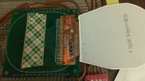
Display attach side 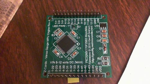
Circuit side After loading the 44 pin driver "Ver 1.10 2016-02-14 Initial Release" and adding the segment and needle subs, I pushed it into the library. On restart, I think the driver is initializing the display OK, but I think the CLS command is not working correctly... 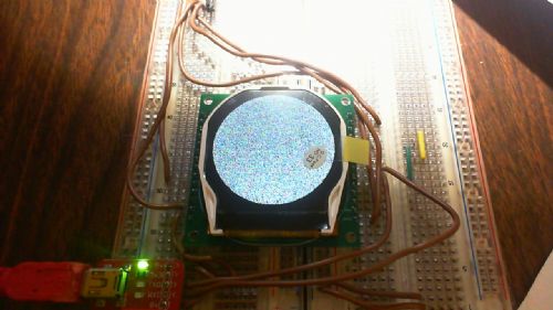
However, when I run the command "gui test lcdpanel", it seems to work ok but when you stop the test, the display doesn't clear to black. 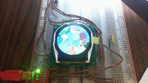
So, next, I tried running the gauge test program and "force cleared" the display by drawing a black circle with max radius of the display. 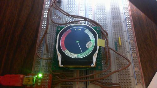
This seems to work OK, so, I think the hardware is working correctly. I also tried changing the orientation of the driver to flip the display view around right side up, but it always seems to be upside down. Also, I tried using different fonts, but only Font #1 seems to work. The 64 pinner driver on the MM+ prototype seemed to use the different fonts OK and the CLS command seemed to function as well. I will let Peter (matherp) take a peek at this and see what he says... @matherp - If you need me to send you a completed PCB to test the driver code, it would be no problem fine Sir..! Just PM your address and it's on the way to you... Thanks for doing all the hard work on the driver. Without your efforts, this thing wouldn't exist... 
P.S. Thanks WW for the USB converter boards... Working good..! EDIT: The display orientation flip does work ok.. Had to restart it.. |
||||
| WhiteWizzard Guru Joined: 05/04/2013 Location: United KingdomPosts: 2991 |
@Zonker; What is the viewing angle like with these TFTs? Also, are they 'bright' enough to be viewable in a well-lit room? (I don't mean in direct sunlight; just consider normal daylight as opposed to a 'darkish' room). Thanks . . . . WW EDIT: Great looking PCB (in the flesh!) |
||||
| Zonker Guru Joined: 18/08/2012 Location: United StatesPosts: 772 |
@WW... Viewing off angle seems to be pretty good with this one and the brightness is plenty good for inside stuff. I haven't tested the PWM drive yet but should work fine. Still, I was hoping for a brighter display overall... I might try "over driving" the the backlight LED's a bit and see if that helps... The Brightest LCD display I'v seen by far is the 2.2" 176x220 parallel type that Matherp found and seems to be well suited for more "daylight" type operation. I also had gotten the OLED type unit to see it's brightness output but was just not impressed with it. It's about the same as many of the LCD units, but I was thinking it would be brighter by far over LCD types, because there would be no polarizing filters and such but, not the case. I think they are not worth the extra cost either... I might have a play with the E-Ink units but they might be even more costly.. The search goes on...
I have enough supplies to build 10 of the Versa Gauge PCB's and sent the first one off to Peter to have a play with. I will need to keep about 5 for doing the EIS project work but there will be a few left if anyone wants one... I will be sending the interface prototype board off to the board house soon to complete a "ready to go" Gauge unit... Ed would need this to complete the 3-D printer work for the "old school" case design... |
||||
| Frank N. Furter Guru Joined: 28/05/2012 Location: GermanyPosts: 1141 |
Hi Zonker, is it possible that you export your very nice board to Eagle? I use Target3001 and can import Eagle files... I bought two of these displays and would be very interested on a PCB for it. Thanks! Frank |
||||
| Zonker Guru Joined: 18/08/2012 Location: United StatesPosts: 772 |
@Frank.. I have parts and PCB's available for the Versa Gauge.. If you like, I could send you a "kit" to solder up, or glue the parts on here... I would be able to part with 2 of them.. No problem.. Let me know and I can ship to you... I will try to export the Dex design files into Eagle format if possible... Will post them if it works..!
@Matherp.. Well, I managed to build up the second PCB and get it programed and tested after Church service this evening... I am happy to report that your driver code seems to be working perfectly..! CLS function works as expected...  I am not sure why it doesn't on the first PCB..??? Maybe a crappy solder joint or funky display... Not sure... I will build up more of them soon.. Attached is the test code... I am not sure why it doesn't on the first PCB..??? Maybe a crappy solder joint or funky display... Not sure... I will build up more of them soon.. Attached is the test code...
2016-03-26_042256_Versa_Gauge_Test_Program.zip |
||||
| Frank N. Furter Guru Joined: 28/05/2012 Location: GermanyPosts: 1141 |
Hi Zonker, many thanks for your efforts! I am very interested in two of your kits (without TFT)! How much would it cost? Do you have PayPal? Thanks again! Frank |
||||
| Zonker Guru Joined: 18/08/2012 Location: United StatesPosts: 772 |
@Frank... Sorry buddy, I forgot to get back to ya.. Best rough guess on parts is about $8.00 US for each kit plus maybe $10.00 to ship it to you.. Now, be aware that these are the first prototype run of the PCB and as such, there are a couple if issues to fix on the next run of boards. Mainly, the interface headers leaving the board... Somehow when I got them back from manufacture, the hole size for the headers is to small for "regular" square pin headers, so I had to use "machine pin" headers to fit into the smaller size holes. Also, there is an extra 0.50 inch offset in the span length between the headers, so the PCB will not fit neatly on 100 center vector boards..  Somehow I missed that..! It will be fixed in the next board run... I am currently using two vector boards sitting next to each other to play around with the Gauge code, so it's not much of an issue... Somehow I missed that..! It will be fixed in the next board run... I am currently using two vector boards sitting next to each other to play around with the Gauge code, so it's not much of an issue...
Anyway, If your OK with the issues, PM me your name and address info and I can get them packed up... @Matherp... I have been playing around with the Gauge code and wanted to try something a little different... Instead of drawing a needle in the center of the gauge, I tried turning the outside part into a radial bar gauge type display with the data displayed as a number in the center... I used the cool 7 segment font and made it color changing as the scale goes up... 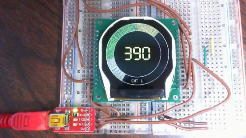
Cautionary part of the scale 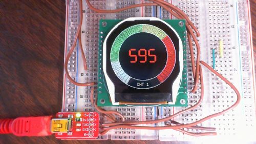
Oh sh*t part of the scale Anyway, still having a good time playing with this..
BTW - I have now got the third PCB built up ad tested. Your driver is working perfectly fine on board #3... All good |
||||
| Zonker Guru Joined: 18/08/2012 Location: United StatesPosts: 772 |
Update... Versa Gauge Dual... 
The code is still kind of a kluge, But getting somewhere...
2016-04-14_020034_Versa_Gauge_Dual_-_User_Input_v1.zip |
||||
| Zonker Guru Joined: 18/08/2012 Location: United StatesPosts: 772 |
Update... Well, the Interface boards finally arrived from the fine folks at Shenzhen and look very good.. I got one built up as a dual thermo K type using the MAX31855 converter IC's fitted to the PCB and will begin tinkering with it tomorrow... 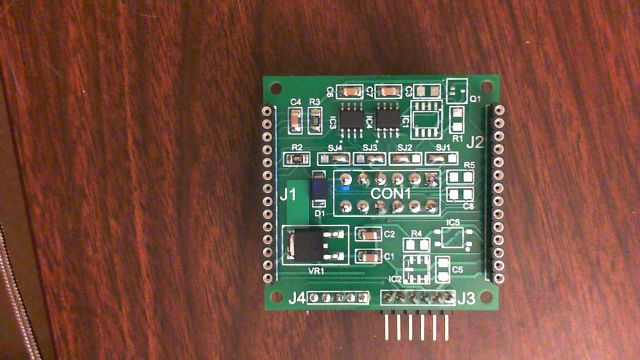
The front side contains the circuitry and meshes together with the back side of the display engine PCB to protect the IC's better... 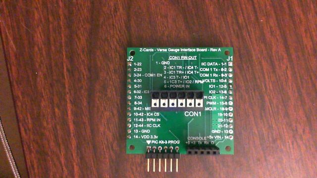
The back side contains the unit's main outside interface connector to supply power and routes the proper signal selections through the "SJ's" depending on how you populate the PCB... This is just a prototype board to allow code writing for several types of input combinations... Should be fun..!
2016-05-21_044410_Versa_Gauge_Interface_Board.pdf |
||||
| The Back Shed's forum code is written, and hosted, in Australia. | © JAQ Software 2026 |
