| Author |
Message |
WhiteWizzard
Guru

Joined: 05/04/2013
Location: United KingdomPosts: 2991 |
| Posted: 09:53pm 21 Mar 2016 |
 Copy link to clipboard Copy link to clipboard |
 Print this post |
|
Hi,
I have two things am trying to resolve regarding a PCB design in Eagle.
1> I need a solderable 'slot' for a components odd shaped leg. How can I create a solderable 'oval' (think rectangle with rounded corners)? I also need to connect a 'signal path' to it for auto routing purposes.
2> I have made multiple pads for another component using the rectangle tool on the appropriate layer (for an SD socket with no .lbr file for that part). But how do I make a rectangle 'connectable' to a signal path so I can autoroute a track to it?
Not yet 'Googled' the above - just thought I would ask you fine folk out there first while I continue with the PCB.
Hopefully someone will know how to help me . . . . .
Many thanks  Edited by WhiteWizzard 2016-03-23 Edited by WhiteWizzard 2016-03-23 |
| |
Zonker

Guru
Joined: 18/08/2012
Location: United StatesPosts: 772 |
| Posted: 03:48pm 23 Mar 2016 |
Copy link to clipboard |
Print this post |
|
Hey WW...
Not much help here... I have ver 5.1 here (kinda old) and tried the slot thing... no help.. Best I could do is a array of holes shaped like a slot.. Board houses will not like that as doing so tends to break the drills... In V5, there is not "mill" type slot objects... What version are you running..? # 2 might be doable... Highlight the pad object and check it's attributes in the editor.. See if you can change it's name value to the net you need to attach to it... (not sure about this) ?? It's probably better to just create the part in the library editor, but maybe the part functions you need to create the objects you want don't exist... V5 that I have is very much the same way and creating strange pads is just not doable.. Dex, being more up to date, lets you do more things with pads and conductive areas in a part design...
I know I am not much help here... But I did have a look at it... 
In the past, I found a website that was a part library database that would convert parts to various CAD formats, but charged you for every finished download.. Bummer.. Nowadays, I am kinda wary about parts from outside, being burnt a few times... Maybe the part you need can be created in Dex and exported into a suitable Eagle part be using one of the many "ULP" scrips out there for Eagle.. UPL's (User Language Programs) look alot like "C" code and call on the vast array of functions inside the Eagle "engine" Check the forum and see if anything gets close... It would take some back ground work, but ULP's are editable and there is information on how to write them...
Anyway, nuf babble... Hope this helps... Edited by Zonker 2016-03-25 |
| |
Emady
Newbie

Joined: 02/02/2016
Location: United KingdomPosts: 23 |
| Posted: 12:30am 24 Mar 2016 |
Copy link to clipboard |
Print this post |
|
Hi WW,
I use Eagle myself but could not figure out how to do what you need. Have you tried the Eagle group on Yahoo?
https://groups.yahoo.com/neo/groups/Eaglecad/conversations/messages
I am sure someone there will know.
Elia |
| |
Grogster

Admin Group

Joined: 31/12/2012
Location: New ZealandPosts: 9985 |
| Posted: 12:40am 24 Mar 2016 |
Copy link to clipboard |
Print this post |
|
I don't use Eagle, but in Sprint Layout, to make slotted holes, I just placed a whole lot of vias side-by-side, and overlapped them such that the holes form a slot. This was accepted fine by the PCB house, and ends up as a plated-through slotted hole.
Eagle may not let you overlap vias like that....
Smoke makes things work. When the smoke gets out, it stops! |
| |
MicroBlocks

Guru
Joined: 12/05/2012
Location: ThailandPosts: 2209 |
| Posted: 01:17am 24 Mar 2016 |
Copy link to clipboard |
Print this post |
|
That is why i choose diptrace.
It is simple and done in about 10 seconds

So far i can create any component and footprint that i want.
Copper can be square, round, oval and polygon.
A hole in the pad is limited to round or oval. That limit is probably also when manufacturing so it might not be a real limit.
If there is one thing i really hate, it is wasting time trying to do something simple. I tried a few schematic/pcb software before deciding on diptrace. I tested with a through hole USB connector with yes oval pads. That was the end for Eagle, could not be done.
Edited by MicroBlocks 2016-03-25
Microblocks. Build with logic. |
| |
Grogster
Admin Group
Joined: 31/12/2012
Location: New ZealandPosts: 9985 |
| Posted: 01:35am 24 Mar 2016 |
Copy link to clipboard |
Print this post |
|
Sprint-Layout method using overlapping vias:
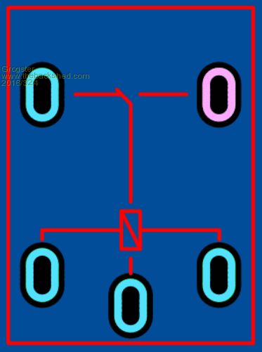
Even though I overlap the vias, when you then click on the whole bunch of them, SL auto-groups them into a slotted hole for you. This is nice, as there is no direct way to specify you want a slotted hole in any of the menus etc, but the intelligence in the software obviously thinks it knows what you are trying to do.
Smoke makes things work. When the smoke gets out, it stops! |
| |
