
|
|
Forum Index : Microcontroller and PC projects : MM Measuring Voltage.
| Author | Message | ||||
| Phil23 Guru Joined: 27/03/2016 Location: AustraliaPosts: 1667 |
Hi all, Just looking for suggestions on the correct way to measure Voltage on my controller. Have a Solar garden light loaded with a 10 Ohm resistor that gives around 1.0 Volts out in good sunlight, closely approximating 1000w/m�. I know I can just hook it to a an analogue pin & read it, but what about buffering & isolation? It will be at the end of about 10m of light twin core, and presume that could create noise issues. Can anyone suggest what supporting circuitry I should use? Very rusty in that department. Thanks Phil. |
||||
TassyJim Guru Joined: 07/08/2011 Location: AustraliaPosts: 6543 |
Start with a series resistor of a few k. I would use 2.2k to 4.7k Finish off with a 0.1uF capacitor to ground to limit the spikes. What voltage do you get with the 10 ohm resistor removed? If you want to cover the possibility of it going open circuit, you need the series resistor big enough to limit current at full voltage. Jim VK7JH MMedit |
||||
| Phil23 Guru Joined: 27/03/2016 Location: AustraliaPosts: 1667 |
With no resistor, just the panel, I easily get a maximum of about 2.6 volts from the cell. Problem is the open circuit with no load is less variable with the level of sunlight, needing not much to reach maximum Open circuit voltage. I found 10 Ohms is a good load to get Solar levels I can relate to my Solar irradiance meter. Edit:- So no need for anything like a unity gain OP amp to buffer the input? Thanks Phil. |
||||
| Phil23 Guru Joined: 27/03/2016 Location: AustraliaPosts: 1667 |
Out of Interest, I'm getting 575Watt/m� at 10:30am; Panels facing N/W with 11� inclination. 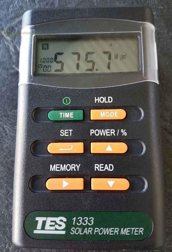
Voltage across the 10Ohm is 780mV, which equates to 60.8mW. 1.0 Volts gives me 100mW, so the figures roughly equate to the Solar energy available. Edit:- Now showing around 700W/m�, 680mV which equates to 70.6 mW's at the resistor. Close enough for the intended purpose. Cheers. |
||||
| TassyJim Guru Joined: 07/08/2011 Location: AustraliaPosts: 6543 |
With 2.6V open circuit, there is no need to worry about high voltages. I would use the 2.2k series resistor and 0.1uF cap. Put them close to the micromite, not at the sensor end. The micromite has a high input impedance so no need for buffer amps. With only 1 volt to play with resolution will not be high. The minimum step the micromite can see is 3.2mV Jim VK7JH MMedit |
||||
| robert.rozee Guru Joined: 31/12/2012 Location: New ZealandPosts: 2541 |
hi, just be aware also, that the output of solar cells may degrade slowly over time, the rate dependant on the technology used. i believe the cheap brown 'printed on the back of a piece of glass' ones are considerably worse in this regard than the blue (crystalline silicon) ones. note: my knowledge of the technology is very dated, newer technologies may have better control over this problem. cheers, rob :-) |
||||
| Phil23 Guru Joined: 27/03/2016 Location: AustraliaPosts: 1667 |
Thanks Rob, I'm open to alternative ideas. At this stage all I can state is that when visually observing the water temp in and out of the panels, depending on ambient temperature, the panels stop heating when the solar panel loaded voltage drops below about 250mV. Have thought about using LDR's, Lux sensors. Basically, I just want a measure of if the sun is shining brightly enough to benefit the heating objective. One thing about solar cells is that they will take in to account, to a degree, is the angle of the sun. It might still be bright, but if it's at a low angle, there is not a lot to be gained. Maybe the best solution is a decent quality solar cell. Cheers Phil |
||||
| The Back Shed's forum code is written, and hosted, in Australia. | © JAQ Software 2026 |
