
|
|
Forum Index : Microcontroller and PC projects : New York Geothermal Control Architecture
| Author | Message | ||||
| Paul_L Guru Joined: 03/03/2016 Location: United StatesPosts: 769 |
I am beginning to write code for this monster, but I don't yet have any MM chips so I am writing it "blind" without being able to check it in any way. I am mostly using Notepad++ as my editor and I have two questions. Has anyone constructed a syntax file for Notepad++ for MMBasic? Is the MMBasic interpreter picky about finding leading spaces or tabs at the beginning of code lines? In other words, can I use either spaces or tabs to indent my code or will the interpreter only accept spaces? |
||||
Grogster Admin Group Joined: 31/12/2012 Location: New ZealandPosts: 9985 |
May I ask why you are not using MMEdit? It's built for the task. You may well have a reason, but that would be the first go-to IDE for the Maximite and Micromite IMHO, and I think everyone else would probably agree - especially if you are not developing directly on the chip using the built-in editor. Smoke makes things work. When the smoke gets out, it stops! |
||||
| Paul_L Guru Joined: 03/03/2016 Location: United StatesPosts: 769 |
@Grogster. I will probably switch to MMEdit but I'm not very familiar with it yet, and I'm adapting code which I previously wrote in Lua for this project. When I started the project I thought it would be based on the PicAxe. That idea ended very quickly. Then I switched to using Lua over Linux running in an OpenWrt router. But that meant switching between Lua and HTML for web page based I/O. That got messy really quickly. Do you know if anyone has constructed a syntax file for Notepad++ for MMBasic, and is the MMBasic interpreter picky about finding leading spaces or tabs at the beginning of code lines? In other words, can I use either spaces or tabs to indent my code or will the interpreter only accept spaces? |
||||
| Paul_L Guru Joined: 03/03/2016 Location: United StatesPosts: 769 |
I am attempting to calculate how much memory my arrays will use. I presume that floating point uses 4 Bytes per value so will an array A(16,4) use 256 Bytes? The manual says that when a constant number is used it will be assumed that it is an integer if a decimal point or exponent is not used. Does that mean that CONST a=4 will store the number 4 in an 8 Byte space? Does that also mean that the statement IF A>4 THEN .... will use 8 bytes to store the number 4 after tokenizing the line? |
||||
| Geoffg Guru Joined: 06/06/2011 Location: AustraliaPosts: 3363 |
Yes, floats use 4 bytes. Unless told otherwise arrays start at zero so your example will have 17x5 elements or 340 bytes. When a variable is created data such as its name, type, etc most also be stored and that takes 48 bytes per variable so the total for DIM A(14.4) would be 388 bytes of RAM. Yes, but because the constant is not a string or array its value will be stored within the variable table so your example will use just 48 bytes of RAM. At this times constants are not tokenised so the number 4 will use one byte of flash memory, the number 1.23 would take four bytes of flash, etc. No additional RAM would be used. I hope that this helps, Geoff Geoff Graham - http://geoffg.net |
||||
| Paul_L Guru Joined: 03/03/2016 Location: United StatesPosts: 769 |
@Geoff, Thanks a lot. I'm trying to figure out how much RAM my arrays will use. Since I haven't decided which implementation of the uM+ I will use I haven't bought the hardware which means that I can't just run a test program and check the memory use directly. I like Grogster's Explore 64 because it will plug into a breadboard, but it doesn't have a real time clock on the board. I also like CircuitGizmo's CGMMICROBOARD2 but I'm not too sure about the Arduino headers interfacing with the mother board I will have to make myself. I have been advised to not build the family of two processor boards, an i/o interface board and a display as a sandwich but to arrange the display and processors side by side on a larger interface board. What do you think? I guess that I will have to wait to get a touch display set up with a processor to see how many variables I can show at one time. There are about 22 primary variables the thing will measure and each will have limits set on setting screens. Did you enjoy the trip to Tasmania a few months ago? |
||||
| Geoffg Guru Joined: 06/06/2011 Location: AustraliaPosts: 3363 |
There is a board coming soon called the Explore 100 which might do what you want. This video provides a short introduction: https://youtu.be/j12LidkzG2A It will feature in Silicon Chip magazine (in Australia) in about eight weeks (no promises but that is the target). At about the same time Grogster will be offering the PCB in various versions including one with the SMD devices soldered and the micro programmed. I am not quite sure what you mean but I like the sandwich approach as everything is held in a rigid assembly with the minimum of cables. The Explore 100 is designed to allow a third board to be added to the sandwich. Tasmania was wonderful and very picturesque. As it happens I am about to set off on another trip to San Francisco, Seattle, Montana and parts of Canada. It is all go, go, go !! Geoff Geoff Graham - http://geoffg.net |
||||
| Paul_L Guru Joined: 03/03/2016 Location: United StatesPosts: 769 |
Geoff, The Explore 100 might be what I need. Thanks for the heads up! I was planning on sandwiching a display, two processor boards, and an interface board containing the power supply, relay drivers, and plug routing for the temperature sensors. I thought that the vertical stack might be a little thick. I then started thinking about a larger interface board above which would mount two Explore 64 boards and the display. The display could be on one side and the processors on the other side by side. I intended having one processor running a loop which can't be delayed and the other handling interrupt driven user input. The display will have to be pretty large, probably 7" or 8". I'm glad the trip to Tasmania worked out. Have a good trip to this part of the world! It sounds like you will not get very far east, but if you do let me know and maybe we can get together. You have my email address, give me a buzz. Paul |
||||
| LouisG Senior Member Joined: 19/03/2016 Location: AustraliaPosts: 130 |
Hi Paul, I’ve been following your ideas and plans, which can really be described as a process control project. Having just applied a Maximite to a small process plant myself may I add a couple of comments? Your idea of a putting the screen, Micromite and interface boards side by side is definitely the way to go. Sandwiching boards for compactness is fine if you are mass producing a product or kit - and rightly so - it saves material, reduces costs and adds marketing appeal. But that is not your case. Yours is a one-off, for your own use. Build it for comfort, not for speed (so to speak). Make the interface board(s) roomy. Make troubleshooting of I/O related problems easy. Add LEDs to all discrete outputs and inputs. Adding miniature PCB toggle switches to every discrete output can help hugely in commissioning and troubleshooting by making testing independent of software. Consider using more robust connectors instead of pin headers and Dupont jumpers. Play safe. Use low voltage for control. I used 24V DC. Keep control and mains voltages on separate boards. Consider fail-safe issues. I avoided open collector output circuits … I didn’t want the loss of a Maximite output signal to cause a tank heating element or a pump to switch on. Keep safety trip circuits hard wired and outside of microprocessor control, e.g. for over-temperature, motor overload, pump dry running, etc. The output board in the photo is to illustrate “roominess”. It uses 50A MOSFETs from Tayda Electronics and is single sided, designed using Visio and made by Sesame. I will be redesigning it, incorporating many lessons learnt the hard way. Louis 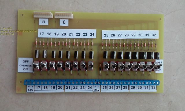
|
||||
| The Back Shed's forum code is written, and hosted, in Australia. | © JAQ Software 2026 |
