
|
|
Forum Index : Microcontroller and PC projects : Castallated holes (PCB)
| Author | Message | ||||
| MicroBlocks Guru Joined: 12/05/2012 Location: ThailandPosts: 2209 |
Does anyone have experience getting a board fabricated that has castallated holes. Like in this picture: 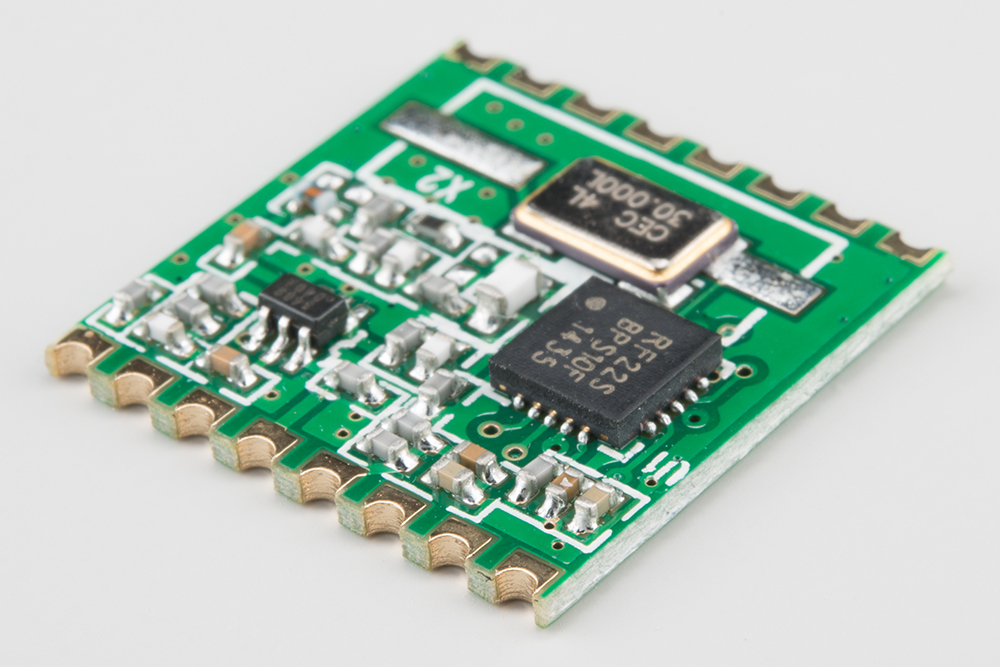
I would like to make a few modules with it to make soldering directly to another board easier. Microblocks. Build with logic. |
||||
CircuitGizmos Guru Joined: 08/09/2011 Location: United StatesPosts: 1427 |
I'm a bit curious, too. Is there an industry standard or best practices guide for these? Some modules that I have dealt with are great to solder, others have been quite poor. Micromites and Maximites! - Beginning Maximite |
||||
| Emady Newbie Joined: 02/02/2016 Location: United KingdomPosts: 23 |
Hi MicroBlocks, I once tried that by creating square vias and then when the PCB came back from China I cut along the via centre line. First tried with shears and wasn't too successful but the second try was with a dremel and cutting disc and I was very pleased with the result. Hope this helps. Elia |
||||
| MicroBlocks Guru Joined: 12/05/2012 Location: ThailandPosts: 2209 |
I tried cutting through normal header pin holes but the result was not very repeatable. I tried it with a cnc which tore of some copper, did it a few times even cutting of a bit less and touch it up with a sander with a fine grid. Last try was with the lasercutter which left a charcoal like edge which needed a lot of cleanup. Those methods are oke for a few but if i need to make more then it is too time consuming. I wish it was an option with the many onine pcb houses so that i have an indication that they do it and at what cost. My chinese is not so good, and US or EU based PCB manufacturers charge insane amounts of money in comparison which would make my modules to expensive. I will try it with a cutting disc when i have my foredom setup ready. Microblocks. Build with logic. |
||||
Grogster Admin Group Joined: 31/12/2012 Location: New ZealandPosts: 9985 |
I have done this on boards before, and I just use normal vias, but ensure that the outline layer cuts right through the middle of them: 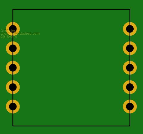
This has always worked for me on the times I needed to do that. Probably not the best way, but it does work. Once cut, the semi-circle remainder of the via becomes the solderable edge of the board. Smoke makes things work. When the smoke gets out, it stops! |
||||
| MicroBlocks Guru Joined: 12/05/2012 Location: ThailandPosts: 2209 |
Did you cut it yourself or did the PCB manufacturer do it for you? Microblocks. Build with logic. |
||||
| Grogster Admin Group Joined: 31/12/2012 Location: New ZealandPosts: 9985 |
PCB manufacturer. They just slice the board where the outline is, and that was right through the middle of the vias. Smoke makes things work. When the smoke gets out, it stops! |
||||
| The Back Shed's forum code is written, and hosted, in Australia. | © JAQ Software 2026 |
