
|
|
Forum Index : Microcontroller and PC projects : Ideas needed for 12v to 3v3
| Author | Message | ||||
| WhiteWizzard Guru Joined: 05/04/2013 Location: United KingdomPosts: 2991 |
This topic has been mentioned several times before in the past; but with hopefully more and more people now using Geoff's MicroMites I thought I would raise it again to see if there are any 'smart ideas' people are using out there! Let me be clear, I have many PSU circuits myself in use - but am asking for 'out of the box' thinking that maybe none of us are using . . . The basic requirement: To run multiple MM circuits around a house at 3v3 from a centralised 12v power supply. More Info: The 12v supply derives from a 240v security PSU (complete with built-in UPS) and is distributed around the house via 2-cores of multiple 8-core security cables. This 12v supply is capable of delivering more than enough current/power to drive the intended MM circuits. The 12v voltage can be considered as stable (and voltage drops at 'far-end' of cables are insignificant). Some of the MM circuits will be 'sleeping' for some of the time and hence pulling sub 1mA. This is important to consider as LDO's often require a minimum current draw to operate correctly. So when the circuit is 'sleeping', the LDO/vReg still needs to operate correctly. Most of the MM circuits will draw no more than 100mA peak (40mA most of the time). I am looking to house the circuit in a TINY enclosure so need these PSUs for these MM circuits to be physically small. Some MM circuits will require peripherals running at 5V (larger enclosure) Two MM circuits will be driving large TFTs (so PSU size is irrelevant(ish)). I could have localised PSUs at those locations but am considering using more than the 2-cores to deliver enough power via the security cables (keeps wiring invisible if I can do this!!) The most common things I have used in the past: 12v-to-9v-to-5v-to-3v3 LDOs (too many components - seems 'messy') Buck convertors (often require largish inductors - and I can often hear these 'whistle') If there was one design to fit all scenarios this would be great. There are many ICs now on the market and it is impossible to know about all of them. SMDs are my preference due to the small size I am trying to achieve for most of the MM circuits. So over to you all - any fresh ideas welcome . . . . . THANKS  |
||||
lew247 Guru Joined: 23/12/2015 Location: United KingdomPosts: 1709 |
How about one of These to drop it to 5V 9A then work from there? or if you want 3.3V at 7A |
||||
kiiid Guru Joined: 11/05/2013 Location: United KingdomPosts: 671 |
R-78E3.3-1.0 All the R-78Exx series are meant to be direct replacement for the 78xx series http://rittle.org -------------- |
||||
Grogster Admin Group Joined: 31/12/2012 Location: New ZealandPosts: 9985 |
How about these 9mm x 17mm modules. 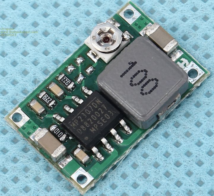
US$2.86 for FIVE modules. 4.75v-23v input, 1v - 17v output. 1.8A continuous, 3A surge. I have not yet found the datasheet for the regulator IC, but am looking for it now. I will post a link once I find it. EDIT: Datasheet Link for the MP2307DN IC.... Smoke makes things work. When the smoke gets out, it stops! |
||||
| WhiteWizzard Guru Joined: 05/04/2013 Location: United KingdomPosts: 2991 |
Thanks for the suggestions so far. @kiiid Have you used these before with a MM circuit? If so, are there any 'negatives' with them? Will study data sheet for minimum current draw required to operate . . . WW |
||||
| kiiid Guru Joined: 11/05/2013 Location: United KingdomPosts: 671 |
I have used them with MM+ and they perform very well http://rittle.org -------------- |
||||
| matherp Guru Joined: 11/12/2012 Location: United KingdomPosts: 11606 |
They look great, the only thing that jumps out is 220uF max capacitive load and I wouldn't use one if using the Micromite's ADC |
||||
| WhiteWizzard Guru Joined: 05/04/2013 Location: United KingdomPosts: 2991 |
Useful to know - for now my MM circuits this is for are not using ADC. With a minimal knowledge of analogue electronics, why would this max capacitive load affect ADC (in simple speak!)? |
||||
| Phil23 Guru Joined: 27/03/2016 Location: AustraliaPosts: 1667 |
Hi Peter, Can you elaborate a little more on best recommendation regards power supply when using the MM's ADC. It's something myself & many others are probably unaware of. Cheers Phil. Edit:- Ditto Simple Speak. Need to supports 5 analogue inputs for thermistors, & 2 for external voltage. |
||||
| matherp Guru Joined: 11/12/2012 Location: United KingdomPosts: 11606 |
Unrelated points. ADC issue is that it is a switch mode regulator and has max ripple of 150mV. If ADC is required I would use a 5V version and then LDO to get a good 3V3 |
||||
| WhiteWizzard Guru Joined: 05/04/2013 Location: United KingdomPosts: 2991 |
An email from our Chinese PCB friends at iTead: 
Do you think they are trying to get me to buy it, or avoid it? |
||||
| lew247 Guru Joined: 23/12/2015 Location: United KingdomPosts: 1709 |
I love their "Chinese English" It's actually pretty good and good advice - power up and set/check the voltage before you connect it to your circuit |
||||
| piclover Senior Member Joined: 14/06/2015 Location: FrancePosts: 134 |
I've been using the LM2594N-3.3 (in its DIP-8 flavour) in several projects and I'm very pleased with the result: all it requires is a Schottky diode (1N5819 for example), a small inductor (100µH or so) and two capacitors (using small Sanyo ones, 220µF-16V). It works even without current drawn, got a low quiescent current, is a switched mode regulator and won't dissipate any measurable heat for output currents in the 100mA or so range (it can source up to 500mA, depending on the inductor limits: I use smaller inductors with lower current limits for low current outputs), even with 12V at the input. |
||||
| The Back Shed's forum code is written, and hosted, in Australia. | © JAQ Software 2026 |
