
|
|
Forum Index : Microcontroller and PC projects : [Microblocks] LCD MX170 backer
| Author | Message | ||||
| MicroBlocks Guru Joined: 12/05/2012 Location: ThailandPosts: 2209 |
(Still have to find a good name that describes this design of this future product.) It is based on the LCD backpack from Geoff but with added functionality. Usage is mainly as a little control box that has all the main features on board. Most pins are available on the 19 pin header for connecting to other modules/parts. Extra on board features are: * Zif socket for direct connection of ILI9341 LCD * 14-pin header for standard ILI9341 LCD carrier boards * Onboard USB-Serial converter (U2SPK chip) * PIC32 Programmer (U2SPK chip) * Keypad or switches 4x4 matrix scanner (U2SPK chip) (in development) * DS3231/2 Real time clock with battery connector * FRAM * EEPROM * Winbond or Microchip Flash * IR receiver * RS485 Half Duplex Transceiver * Compact size of 50x50mm. Schematics: 2016-07-24_233736_DipTrace_Schematic_-_LCD24-170.pdf The keypad matrix scanner injects ASCII code into the serial buffer so keys can be read with standard INPUT or INKEY$ commands. It allows between 1-16 switches or keypads which are also debounced, without the need of any programming in the micromite. 3D top view: 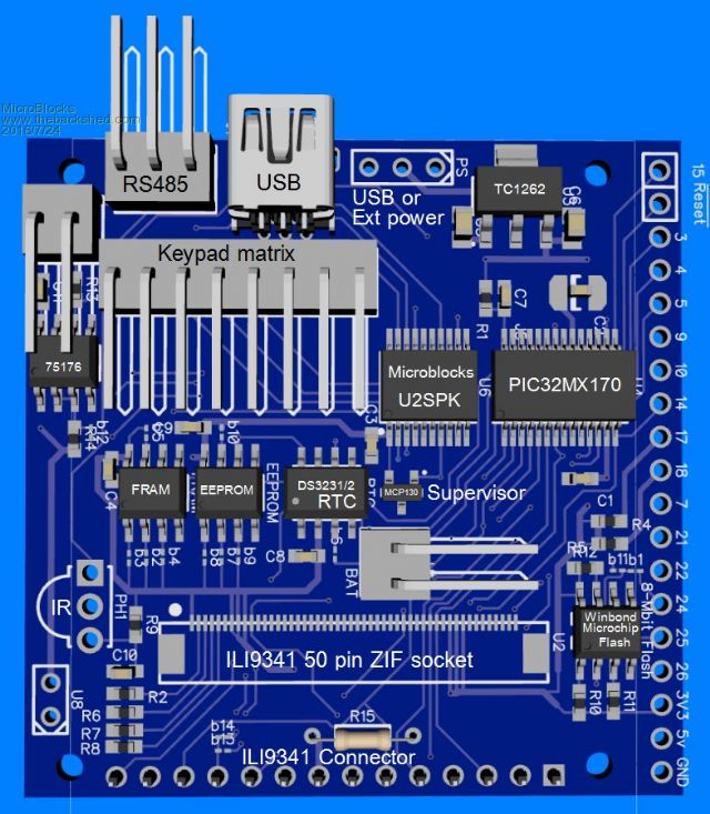
I would appreciate some extras eyes going over the schematics, especially the RS485 and ILI9341 connectors. Microblocks. Build with logic. |
||||
bigmik Guru Joined: 20/06/2011 Location: AustraliaPosts: 2981 |
GDay MicroBlocks, Whilst I usually use only the 4 wire RS485 form, I think you need to use an inverter on the DE/RE line of your RS485 chip. Kind Regards, Mick Mick's uMite Stuff can be found >>> HERE (Kindly hosted by Dontronics) <<< |
||||
| bigmik Guru Joined: 20/06/2011 Location: AustraliaPosts: 2981 |
MicroBlocks, I also think that the resistor controlled by U8 needs to be a PULL-DOWN to enable Receive as the default state if you are not sending any data.. I suppose it all depends on the logic of what you are intending to do with your controller as to whether you want to have it set for transmit only if P7 is not (I assume it is a solder pad pair) shorted or as receive only, maybe U8 needs to be a 3 pin for pull up or pull down depending on the application.. But logically if P7 is left open the circuit can only ever be a one way communication so I wonder about the logic of having it. Kind Regards, Mick Mick's uMite Stuff can be found >>> HERE (Kindly hosted by Dontronics) <<< |
||||
| MicroBlocks Guru Joined: 12/05/2012 Location: ThailandPosts: 2209 |
You are right about the need to invert the DE signal on pin 7. The Maximite was active high, the micromite is active low. Bummer. Pin7 is connected to the transceiver with a solder bridge. If the transceiver is not used then Pin 7 can be used as a normal pin on the extension header. So only when the chip is mounted close the solder bridge. U8 (should be a J refdes btw) is used to provide an external power for the transceiver. Not clear in the schematics, i have to make that better! If it needs a bit more power then the USB can deliver, this is the pin to use. If USB power is used then U8 is shorted with a jumper. PCB space is already tight and i need to add an inverter for the DE signal. What would be the smallest solution? Microblocks. Build with logic. |
||||
| bigmik Guru Joined: 20/06/2011 Location: AustraliaPosts: 2981 |
@MB, If you intend U(J)8 to be a power input I reckon you need a GND there as well. I don't really like things such as (run 5V to the TOP pin) i.e. only 1 wire. Also if the chip is running off 5v and the levels are 5V then you should put a 1k on the Receive line. Mick Mick's uMite Stuff can be found >>> HERE (Kindly hosted by Dontronics) <<< |
||||
| MicroBlocks Guru Joined: 12/05/2012 Location: ThailandPosts: 2209 |
Good point, i will add a GND to it. I am also thinking about removing the pullup resistor, if com1 is used for Rs485 then pin 7 will have the right level. And pin 7 is not 5v tolerant! COM1 which is used for the RS485 has 5v RX and TX tolerant pins, so i left out the resistors. Microblocks. Build with logic. |
||||
| bigmik Guru Joined: 20/06/2011 Location: AustraliaPosts: 2981 |
@MB, Having a quick look on Element14 site and I see this little beastie 74AHC1G04GW But I would run it off 3v3 as at 5v operation it expects a High INPUT to be 3.85v. It is SMALL (3mm x 1.5mm + leg length) and cheap (unit QTY at $0.55AUS, 100 QTY at $0.23AUS) and I am sure you will find cheaper over in Siam. I think there is enough room to fit an ENIAC on board there Jean.   
Kind Regards, Mick Mick's uMite Stuff can be found >>> HERE (Kindly hosted by Dontronics) <<< |
||||
| bigmik Guru Joined: 20/06/2011 Location: AustraliaPosts: 2981 |
@MB, You could actually add a fourth pin (5v) onto J7 and turn it into the Power input as well, then J8 will simply become a USB powered jumper) Ahh, True I was thinking about console use.. You are right no need for a 1k. Kind Regards, Mick Mick's uMite Stuff can be found >>> HERE (Kindly hosted by Dontronics) <<< |
||||
| Zonker Guru Joined: 18/08/2012 Location: United StatesPosts: 772 |
Peter used a DTD543ZETL transistor that has the resistors inside the part, and is very small... I have started using it, and seems to work fine... |
||||
mikeb Senior Member Joined: 10/04/2016 Location: AustraliaPosts: 180 |
What are the chances of Geoff inverting the DE pin in firmware ? I'm a big fan of NOT using an inverter in hardware. There are 10 kinds of people in the world. Those that understand binary and those that don't. |
||||
| Geoffg Guru Joined: 06/06/2011 Location: AustraliaPosts: 3363 |
In the Micromite MMBasic uses the hardware RS485 functionality in the MX170 chip to generate the DE signal and that does not have the ability to invert the signal. Geoff Geoff Graham - http://geoffg.net |
||||
kiiid Guru Joined: 11/05/2013 Location: United KingdomPosts: 671 |
Ok, here is a little trick here, which I have been using for years and will share now. You don't need an extra control pin for the RS-485 interface, and can use it with a normal UART (or COM port in MM). It requires a bit more untraditional connection of the transceiver, but only one external transistor is everything necessary. You can ignore the part on the RS-485 side, it is my schematic, but yours can be different. Note the left side in the schematic where is the actual difference. Again, this has been tested in a number of designs over years and it 100% confirmed functional. I have tested it with MM as well. 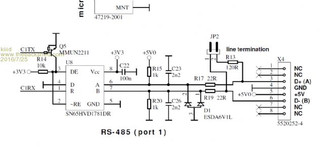
http://rittle.org -------------- |
||||
| mikeb Senior Member Joined: 10/04/2016 Location: AustraliaPosts: 180 |
@geoff Thanks Geoff. Inverter it is. @kiid I've used RS485 transceivers for years and have never dreamed of connecting one this way. Never had to I guess. Well done for ingenuity. 
There are 10 kinds of people in the world. Those that understand binary and those that don't. |
||||
| MicroBlocks Guru Joined: 12/05/2012 Location: ThailandPosts: 2209 |
Thanks Kiiid, that is a neat trick! I am reconsidering including RS485 on the board itself as in most cases it would be better to have an isolated transceiver. I am thinking about using this little control board as a slave or master as part of a network that has sensors, valves and other fun stuff over undetermined distances in and out of the house. And with this trick i can use either com port leaving the DE pin available. Microblocks. Build with logic. |
||||
| MicroBlocks Guru Joined: 12/05/2012 Location: ThailandPosts: 2209 |
@Kiiid, Which of the mmun2211 should i use? There are a whole bunch of different ones with specific resistor values. Some of them have resistors that are equal and some have a 1:10 ratio. I am also not able to source them locally. Would this (KRC102-AT/P with 10k resistors) be a good substitute? Unfortunately minimum order is 100 so getting one that is equivalent would be nice. :) 2016-07-26_165533_KRC101-106.PDF I decided to leave the RS485 on the board. If isolation is necessary then that can be done better with an add-on board. Microblocks. Build with logic. |
||||
| kiiid Guru Joined: 11/05/2013 Location: United KingdomPosts: 671 |
You don't need to use that particular type. I only use because I like the biasing resistors inside, but their values are not critical. I guess most models will work fine. You can also replace it with any n-channel mosfet. http://rittle.org -------------- |
||||
| MicroBlocks Guru Joined: 12/05/2012 Location: ThailandPosts: 2209 |
Made some changes. Added a 4017 chip to allow for a 10x8 matrix. This allows for 1-80 switches to be scanned which should be enough for a small full keyboard. Schematic(red areas still to be done/checked): 2016-07-26_220926_DipTrace_Schematic_-_LCD24-170.pdf 3D (LCD display will be on the other side, this has all the headers to see if it all fits. Most headers can be straight or 90 degree to allow for lower profile. 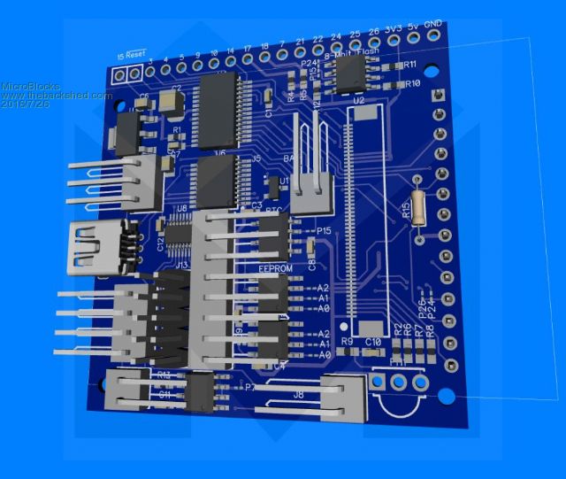
I will have to wait for some parts to do the final measurements. Microblocks. Build with logic. |
||||
| The Back Shed's forum code is written, and hosted, in Australia. | © JAQ Software 2026 |
