
|
|
Forum Index : Microcontroller and PC projects : Micromite & PIC16F1455: Great together
| Author | Message | ||||
| matherp Guru Joined: 11/12/2012 Location: United KingdomPosts: 11608 |
In this thread I posted an open source version of the USB/UART/PICProg32 application which acted as a USB to serial converter for the Micromite and also was able to re-program the Micromite firmware using Rob and Serge's excellent PIC32Prog application. Refer to this original post for wiring details. Since then I've been working with BigMik and Robert.Rozee to further enhance the program. The big issue in all previous versions was the need to have some sort of programmer to get the code into the PIC16F1455 in the first place and then update it if required. This version addresses that in two ways. First, we have developed a Basic program that can run on the Micromite that will program a new PIC16F1455 or re-program an existing one using nothing other than a 10K resistor and a 9V battery (PP3 or similar) Second, we have included in the PIC16F1455 code a bootloader that means that the Micromite can update the PIC16F1455 application without even removing it from circuit when wired to provide the normal USB-serial functionality. This now means that with just one Micromite (any type) or one programmed PIC16F1455 you can then program unlimited numbers of additional chips of both types without any requirement for a PicKit or any other type of programmer. Attached are two project directories that contain the source of the USB/UART/Prog code and the PIC16F1455 version of the freeware DS30 bootstrap 2016-09-17_094743_usb-uart-progV1.17.zip 2016-09-17_094815_firmware_PIC12F_PIC16F.zip and also the PIC16F1455 hex file containing both the application and the bootstrap 2016-09-17_095747_PIC16F1455V1.17.zip Other changes to the application include some minor performance tuning and now in UART mode the LED blinks whenever serial communication between the Micromite and the PIC16F1455 occurs so you can easily see if commuunication is taking place. The other functionality remains the same: When in USB/UART mode: To enter programmer mode press the program select switch briefly, the LED will light. Pressing the program select switch for greater than 2 seconds will reset the Micromite but not enter programmer mode. The LED will flash briefly after 2 seconds to indicate success. A "break" command sent from the terminal emulator can also be used to restart the Micromite (Alt+B in Teraterm). When in programmer mode: Pressing the program select switch for greater than 2 seconds will exit programmer mode. The LED will go out after 2 seonds to indicate success and when the switch is released the Micromite will be reset and the PIC16F1455 will switch back to USB/UART mode 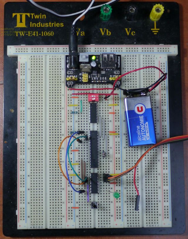
The picture shows my development environment. The bottom PIC16F1455 chip is providing the serial connection to the PC. The top one is wired ready to be programmed. Before anyone asks, I use LEDs with built in resistors for prototyping which is why the green LED is connected direct to the Micromite - makes life much easier 
The wiring and programming process is simplicity itself. PIC16F1454/5 connections: Connect GND to pin 14 Connect 3.3V to pins 1 and 11 Connect PGC (pin 9) and PGD (pin 10) to two Micromite output pins. I've used pins 25 and 26 respectively. Connect a 10K resistor between GND and pin 4 Make sure there are no other connections to the PIC16F1455 Connect the negative terminal of a 9V PP3 Battery to GND (MN1604, PP3-HP, 006P, 6LR61, 6LF22, 6LF62) Have a wire on the positive terminal that you can connect to pin 4 of the PIC16F1455 when requested by the program, a simple SPST latching switch is ideal for this as in the picture. Type run Follow the instructions The programming session produces the following output 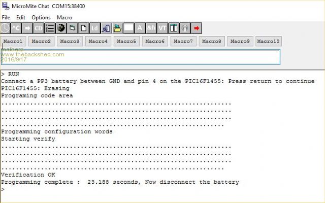
and the PIC16F1455 is then programmed ready for use. Any subsequent updates to the PIC16F1455 code can be done using the bootstrap loader so no need to run this program again. The Micromite code to program a PIC16F1455 is attached. NB all the above also works with the 16F1454, 16LF1454, and 16LF1455. 2016-09-17_101333_pic16f1455prog.zip |
||||
| Phil23 Guru Joined: 27/03/2016 Location: AustraliaPosts: 1667 |
Just curious about your development environment Peter, Is there a specific reason for using the 2 red wires to bridge the power rails instead of setting the left jumper to 3.3V. Is that a better practice for some reason. 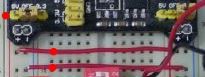
Thanks Phil. |
||||
| matherp Guru Joined: 11/12/2012 Location: United KingdomPosts: 11608 |
No, it is just a legacy of having the power supply in the rightmost position with the right-hand power rails at 5V |
||||
| robert.rozee Guru Joined: 31/12/2012 Location: New ZealandPosts: 2541 |
here are the micromite basic programs required to update the USB/UART/ICSP application in a 1455 that already has a DS30 serial bootloader installed. note that the 1455 must already have the DS30 bootloader present, see 2016-09-17_095747_PIC16F1455V1.17.zip in peter's posting above. 2016-09-18_025443_v115_and_v117_w.loader4.zip these basic programs have been written for situations where the MX170 and 1455 are on a single board together, such as Mick’s MuPV3: 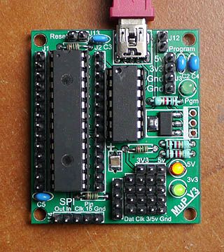
the update process is fairly simple: 1. ensure the console baud rate is set to 38400, ie Option baudrate 38400 2. load the update file into the Micromite using AUTOSAVE or XMODEM. if using AUTOSAVE remember to press ctrl-Z to finish the upload - i just drop the basic file onto the teraterm window, then press crtl-Z when the upload is done. 3. at the command prompt type "UPDATE" and press return 4. follow the onscreen instructions below is a teraterm log of the update process running: > update
checking update data....................... passed autorun has been enabled v1.17 update Instructions: ============= 1. Power cycle the Micromite and PIC16F1455 together, i.e. unplug the USB connection, then plug back in. 2. The update will run automatically and is completed when you hear the Windows USB driver loaded sound. This should take just under 30 seconds. 3. Reconnect the terminal session if TeraTerm/MMEdit does not do so automatically. The new 1455 firmware is now loaded. ************************************************************* *** Unplug the USB connection NOW, plug in again and wait *** *** 30 seconds for the 1455 firmware upgrade to complete. *** ************************************************************* update to v1.17 completed, press any key... update to v1.17 completed, press any key... update to v1.17 completed, press any key... update to v1.17 completed, press any key... update to v1.17 completed, press any key... > there may still be a few small hiccups to iron out. i've done all my testing with teraterm, and had a couple of reports that it also works ok with mmedit. included in the .zip file are versions 1.15 and 1.17 of the application. the only real difference is that 1.17 flashes the LED for serial traffic, whereas 1.15 does not. you can play around swapping back and forth between the two. cheers, rob :-) |
||||
| The Back Shed's forum code is written, and hosted, in Australia. | © JAQ Software 2026 |
