
|
|
Forum Index : Microcontroller and PC projects : Tiny 3A adjustable regulator for $1...
| Author | Message | ||||
Grogster Admin Group Joined: 31/12/2012 Location: New ZealandPosts: 9985 |
I have bought some of these to play with, but I am suitably impressed with the price-point vs regulator ability and current output. Impressive $1 regulator modules. They appear to use the MP2307 buck-regulator IC, and this regulator chip is capable of up to 3A output. These modules cannot do that kind of current, but even if you can get, say, 500mA out of it for the price....... And all the associated caps and resistors done for you - plug and play.  The MP2307 can use a Vin of 4.75v to 23v, and a Vout of 0.9v to 20v Quiescent current of this one is 1.3mA typical, so not as good as some LDO regulators at about 200uA or so, but still four times better then the 5mA or so of the 1117 regulator and seven or eight times better then the LM78xx series. Me like these ones, as they will make ideal on-board regulator modules for lots of stuff, and being so cheap, they work out cheaper then just my current weapon of choice regulator IC alone, and that is for an assembled module! I expect they mass-produce this one in the hundreds of thousands of units(if not millions), so that is why the price is so cheap. Smoke makes things work. When the smoke gets out, it stops! |
||||
redrok Senior Member Joined: 15/09/2014 Location: United StatesPosts: 209 |
Hi Grogster: What makes you think it can't run at 3 amps? The spec sheet says it can. MPS2307 It is a switching regulator. redrok |
||||
| Grogster Admin Group Joined: 31/12/2012 Location: New ZealandPosts: 9985 |
Only lack of heatsinking in this particular tiny package. Realistically, you could expect an amp or so no problems, but pushing it to 3A might prove to be a problem becasue of lack of room for any heatsinking. However, the 2307 does have an exposed bottom thermal pad, and this looks like it is soldered and coupled to the bottom ground-plane to use as a heatsink, so you might be able to get upwards of 2A out of it as-is. 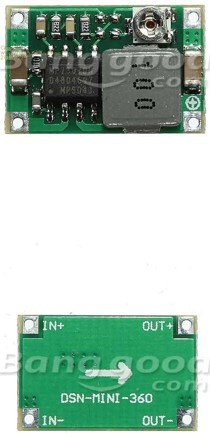 Smoke makes things work. When the smoke gets out, it stops! |
||||
Bryan1 Guru Joined: 22/02/2006 Location: AustraliaPosts: 2138 |
I was needing a stable psu to play with as I have fun trying to get the 64 board to play properly so ordered a batch of those reg's. Will wait until they arrive and in the meantime go back to 8 bit pic's that I used for years. |
||||
| redrok Senior Member Joined: 15/09/2014 Location: United StatesPosts: 209 |
Hi Grogster; First order power dissipation calculation: In this type of switcher the current flow is constant and time divided between the high and low side MOSFETs. So assuming 3A and a body resistance of 100mO: I^2 * R = W 3^2 * .1 = .9W ( neglecting switching losses and other resistances) The spec sheet asks for a 1"^2 PC Board for reliability. This board is: .67" * .43" = .29"^2 .29"^2 / 1"^2 * .9W = .26W derated power (.26W / .1)^.5 = 1.61A derated current for the small board. It would seem that this PC board could be silicone glued to an aluminum plate with Kapton tape sandwiched in there and get full current capabilities. It also might be good to add the Schottky diode D1 as suggested in the spec to improve efficiency. It looks easy to do. BTW, I would hope the inductor is up to par with 3A. redrok |
||||
| Grogster Admin Group Joined: 31/12/2012 Location: New ZealandPosts: 9985 |
Awesome - thanks for the maths, that really helps explain the derating well. I was about 400mA off with my guess of about 2A allowing for the bottom copper as a small heatsink.  Smoke makes things work. When the smoke gets out, it stops! |
||||
| Bill7300 Senior Member Joined: 05/08/2014 Location: AustraliaPosts: 159 |
Handy to have a few on hand and in lots of 5 for around USD5.00 including postage, no great load to carry either. Any idea of their noise generation, RF-wise? Bill Bill |
||||
| redrok Senior Member Joined: 15/09/2014 Location: United StatesPosts: 209 |
Hi Bill;Well it is a switcher. It runs at about 340kHz. The graph appears to have a ripple voltage of about 5mV. I would not use a switcher by itself in an RF application. Their is just to much noise. However, there are methods. Yes, they are efficient. So what can be done? 1. Full RF shielding is a must. 2. Input and Output filters specifically for the switching frequency help a lot. 3. For the most critical applications post low dropout linear regulators work very well. If the switcher is set to be a bit higher than the linear's output there won't be much wasted power. What RF applications do you have in mind? redrok |
||||
| Bill7300 Senior Member Joined: 05/08/2014 Location: AustraliaPosts: 159 |
No particular RF application in mind at this time, redrok but RF noise generation is an always present concern in my normal aviation/avionics and amateur radio pursuits. Bill Bill |
||||
| Grogster Admin Group Joined: 31/12/2012 Location: New ZealandPosts: 9985 |
Have to agree with redrok on that point. For RF work, you really can't beat a gold old linear regulator to keep the supply clean, which is really important with RF stuff, so that you are not radiating more SMPSU noise then wanted signal.  I was thinking more for those who want to run relays, motors, solenoids, stepper-motors etc. Just about anything except RF stuff, really. As redrok says, even SMPSU's are not a problem with RF if they are correctly filtered and sheilded, but this module has neither, so probably not a good idea to try to run you 2W data link off them.  Smoke makes things work. When the smoke gets out, it stops! |
||||
bigmik Guru Joined: 20/06/2011 Location: AustraliaPosts: 2981 |
Hi Grogs, All, Even cheaper.. $1AU ~ $0.76US And then there are these (about 5mm wider and higher -- 0.2") but seem to have the diode mentioned by redrok. DC-DC Regards, Mick Mick's uMite Stuff can be found >>> HERE (Kindly hosted by Dontronics) <<< |
||||
| Grogster Admin Group Joined: 31/12/2012 Location: New ZealandPosts: 9985 |
Nice find, Mick.  I like those listings, cos they give you the module dimensions. That will allow me to whip up a footprint for the ones I have coming. Smoke makes things work. When the smoke gets out, it stops! |
||||
| matherp Guru Joined: 11/12/2012 Location: United KingdomPosts: 11608 |
The problem with all these modules is that they advertise "variable" output voltages but when you look at the datasheets you will see the inductor and other support components should be optimised for a specific output voltage. I've got some of the second boards listed by Mick and my ones have a 4.7uH inductor. Looking at the datasheet for the MP1584 controller chip used this is specified for 1.8-2.5 volts output! Using the boards outside this range will decrease efficiency, increase output ripple, and reduce power capability. The datasheet for the LM2596 explains this very well, see the charts on page 19. This datasheet also explains the best types of inductor to reduce EMI I'm just about to layout a board using the LM2596 and because I know the input voltage will be 12V and I need a 5V output and I know the maximum output I need will be 1A, I can pick an optimum inductor and get best efficiency. |
||||
| Grogster Admin Group Joined: 31/12/2012 Location: New ZealandPosts: 9985 |
Yes, I guess that is definitely one "Gotcha!" with adjustable SMPSU modules of this type. I guess that for one buck...... Smoke makes things work. When the smoke gets out, it stops! |
||||
| The Back Shed's forum code is written, and hosted, in Australia. | © JAQ Software 2026 |
