
|
|
Forum Index : Microcontroller and PC projects : Curiosity PIC32MZEF Development Board
| Author | Message | ||||
| cdeagle Senior Member Joined: 22/06/2014 Location: United StatesPosts: 268 |
I have been able to program the new Microchip Curiosity PIC32MXEF development board with MMBASIC eXtreme MMX5.4.04. I had to solder pins at the ICSP location in order to program with the PicKit3. I used the J12 usb socket and placed jumper J8 between VIN and VBUS. I have tested the board with several of my astronomy programs without any problems. The board includes usb, wifi and two mikroBUS locations. I paid $41 for the board directly from Microchip. |
||||
drkl Senior Member Joined: 18/10/2015 Location: HungaryPosts: 102 |
Hello, MM+,MM-extreme boards from Microchip Microchip distributes two training panels that can run MMBASIC. Both cards have two MicroBUS (MBUS) sockets developed by MIKROELEKTRONIKA, which can be used to test and fit many peripherals. This is essentially a 2x8-pin connector, here you will find the most common communication connections of a microcontroller: SERIAL, I2C, SPI and other signals: AN (ALOG), RESET, PWM, INT and power points: + 5V, + 3.3V, GND. An ever-expanding list of microbus panels can be found here: clickboards The boards include an integrated programmer/debugger , so very easy programm with Microchip�s MPLAB� X IPE. MMPlus can be run on the Microchip DM320103 development board: Curiosity PIC32MX470 DEVELOPMENT Board-DM320103:DM320103 Multiple connectors on the panel allow flexible use. Using the programmable micro-USB connector on the panel, MMBASIC can easily be loaded into the chip using the Microchip MPLABX IPE program. Type of microcontroller on the panel: PIC32MX470F512H-120/PT Through a serial USB converter we can communicate through the MM console port: Name / chip pin / panel --------------------------------------------- Console TX / pin58 RPF0 / U1TX - MBUS1 TX pin Console RX / pin6 RPG8 / SDO2 - MBUS2 MOSI pin Using the USB device connector, you can direct connect to the USB port instead of the console. The table summarizes the terminals compared to the standard 64-pin MM64plus terminals: 2017-06-23_125938_mchipmmplus64pins.pdf It can be seen that the panel provides two SPIs, two I2C and two serial peripherals for MMBasic based development, as well as built-in 5 LEDs and one pushbutton. Additional 4 freely programmable I/O pins are available via the J17 connector. MMPlus eXtreme can run on the Microchip DM320104 development board: Curiosity PIC32MZEF DEVELOPMENT Board-DM320104:DM320104 Similarly as above, the programmable micro-USB connector on the panel, MMBASIC can easily be loaded into the case using the Microchip MPLABX IPE program. Multiple terminals on the panel allow flexible use. Type of microcontroller on the panel: PIC32MZ2048EFM100 We can communicate through the serial port via a serial USB converter via the MM console port: Name / chip pin / panel ------------------------------------------------ Console TX / pin85 RPF0 / ETXD1 - MBUS1 TX pin Console RX / pin86 RPF1 / ETXD0 - MBUS2 MOSI pin Using the USB device connector, you can directly connect to the USB port instead of the console. Since the structure of the panel is very similar to that described above, only the connector connections are given: 2017-06-23_130532_mchipmmextr100pins.pdf drkl |
||||
| cdeagle Senior Member Joined: 22/06/2014 Location: United StatesPosts: 268 |
drkl, Thanks for the additional information about MMBASIC-compatible Microchip boards. |
||||
| cdeagle Senior Member Joined: 22/06/2014 Location: United StatesPosts: 268 |
The Microchip Curiosity PICMZEF development boards seems to load MMBASIC programs using Jim's MMEdit almost twice as fast as the 144 pin MMX board. Ports in both cases running at 38400. |
||||
| cdeagle Senior Member Joined: 22/06/2014 Location: United StatesPosts: 268 |
I have added a DS3231 RTC to the first mikro-BUS (J5) of this board. It can be initialized with OPTION RTC 67, 66. Here's a picture of the RTC on the Curiosity Board. 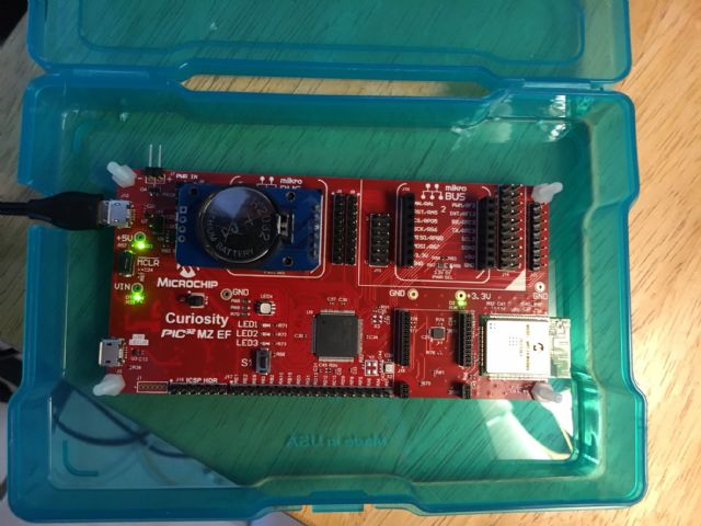 |
||||
| cdeagle Senior Member Joined: 22/06/2014 Location: United StatesPosts: 268 |
Just like Linux, I know just enough about hardware to be dangerous. I'm struggling to find the proper OPTION SDCARD parameters to configure the mikroBUS SD click card for this development board. I have the SD click in the second socket (J10). Any help is sincerely appreciated. David |
||||
| Frank N. Furter Guru Joined: 28/05/2012 Location: GermanyPosts: 1078 |
Hi David, did you tried both sockets? The second socket (J10) uses SPI2, the first (J5) use SPI1. The CS-Pin for SPI2 is Pin82 for SPI1 it's Pin81 but you can use any pin as CS when I anderstand OPTION SDCARD right... - but it seems that you must use the right SPI port!!! Frank |
||||
| Turbo46 Guru Joined: 24/12/2017 Location: AustraliaPosts: 1685 |
cdeagle, you may be able to help on this post Bill Keep safe. Live long and prosper. |
||||
| The Back Shed's forum code is written, and hosted, in Australia. | © JAQ Software 2026 |
