
|
|
Forum Index : Microcontroller and PC projects : My Explore28 project
| Author | Message | ||||
GoodToGo! Senior Member Joined: 23/04/2017 Location: AustraliaPosts: 188 |
Howdy all, As alluded to on another thread, I have been spending waaaaaaay too much time reinventing the wheel and building a Remote power supply controller/monitor to power my Xmas Inflatables. Anyone who has these fan driven monstrosities knows that eventually the fan gets a gut full of water from the summer storms we experience down here in Sunny Melbourne. When this happens, the fans don't short-circuit, they just tend to run slowly, drawing a fair amount of current, which eventually turns the fan into a molten lump of plastic. I find if rescued in time, the fans can be resurrected by drying them out. So the purpose of this module is two-fold. 1) To provide the necessary 12VDC to operate the fans, 2) To monitor the current draw and trip the relay if an overcurrent situation is detected. So in true GTG! fashion, I've gone overkill. 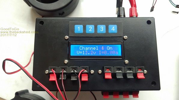 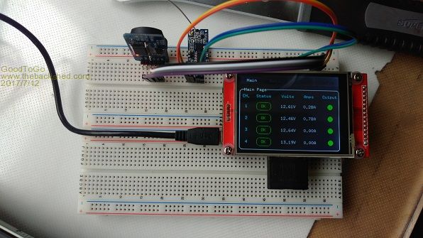 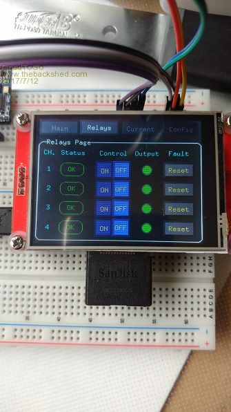 Features -4 separate 34VDC-12VDC supply 'Channels' -I2c relay control -temp monitoring -variable fan speed control using PWM depending on temperature -fan supply uses all 12v channels via diode separation -wireless comms using HC12 -I2c 16x2 LCD display for local monitoring -LCD Display backlight timeout -4 local switches for relay on/off/reset/LCD backlight control -Can run independant of GUI monitoring unit Also, the GUI monitoring unit features -Wireless comms using HC12 -Overcurrent trip points adjustable -'Auto' trip point adjusting routine -SD card logging of all data - time stamped (RTC) -various displays showing power supply/relay status (OK, TRIP, FAIL) -GUI LED indication of status (Green ON/OFF, RED for stuck relay ON) -Voltage/Current/Max Current/ Startup Max Current displays -Full control of 'slave' power supply unit(s) Inside the box:- 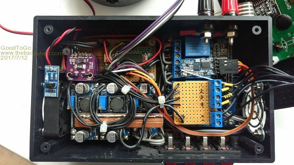 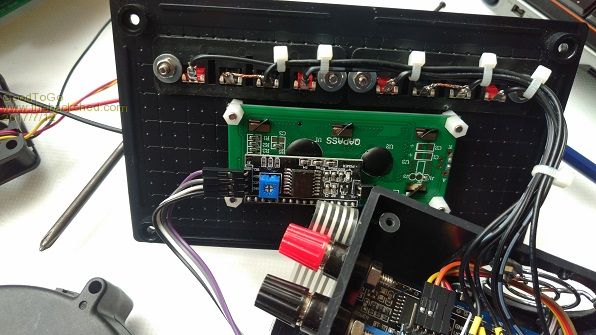 It's a mess.  It's amazing how you think you lay something out nicely, but once you throw the point to point wiring in it rapidly becomes a nightmare! Most modules are ebay sourced. -relay unit. -2x LCD I2c modules. (One converted to drive the relays) -4x INA219 modules (stacked on top of each other) to monitor voltage/current -DS18B20 temp module (on top of fan) -HC12 module with a straight wire for antenna (might go back to the spring one) -Fan driven by TIP120, controlled by the MM -You-beaut Explore28 module hidden in there somewhere as well -5x Buck power supplies. (2x2 stacked on top of each other providing 12V, one by itself supplying 5V for MM) -16x2 LCD module -Stick on Membrane switches As far as the GUI side of things goes, well, it's just a MM+ LCD backpack, coupled with an RTC module and a HC12 module. I have to build two of the slaves units because I have 7-8 inflatables to power on both sides of the garden. I power the whole lot (including stupid amounts of LED lights) by a DELL laptop power supply (19.5VDC), driving a Boost converter set at 34VDC. This is then distributed around the garden as required. It eliminates the 240VAC power leads and crap I used to have spread everywhere...... Cheers! GTG!  ...... Don't worry mate, it'll be GoodToGo! |
||||
mikeb Senior Member Joined: 10/04/2016 Location: AustraliaPosts: 177 |
Nice how you made it all fit in the Jiffy box. Well done.  Necessity is the mother of all invention. It's not overkill. You do it...............because you can. Regards, Mike B. There are 10 kinds of people in the world. Those that understand binary and those that don't. |
||||
Grogster Admin Group Joined: 31/12/2012 Location: New ZealandPosts: 9931 |
Nice work.  I also think it looks quite neat, considering how much stuff you have in there! Smoke makes things work. When the smoke gets out, it stops! |
||||
| WhiteWizzard Guru Joined: 05/04/2013 Location: United KingdomPosts: 2962 |
A great project there - and a nice little overview. Please do post some photos of your garden come Christmas time! One question if I may: Why 34v? I ask because I am doing some LED garden lighting (MM controlled of course) and these APA102 strips require 5v. I am not wanting to lay 230v around the garden (illegal now to DIY this), and wanted to distribute 5v - however I am worried about the voltage drop over a 30m length (current draw can be significant). Considered 12v 'loop' but then the 12v-to-5c circuit would waste too much energy (heat). So I guess 34v is for some of your 'non-LED stuff' but thought I'd ask you anyway . . .  WW |
||||
| GoodToGo! Senior Member Joined: 23/04/2017 Location: AustraliaPosts: 188 |
All of the LED strings I am currently using are a supermarket brand that used old school transformers that output 22-24VAC. Internally the controllers full wave rectify the input, and so run on 32-34VDC. Doing it the way I've done means I have eliminated around 18 plug in powerpacks. Not too mention only having 2 core garden light wiring outside now instead of 240VAC power leads, powerboards, etc....So all lighting runs 32-34VDC, all inflatables run 12VDC. I'll scrounge around for a couple of photos from last years effort and post 'em up. Cheers, GTG! ...... Don't worry mate, it'll be GoodToGo! |
||||
| davematt Regular Member Joined: 27/09/2011 Location: AustraliaPosts: 55 |
@ GTG Wondering if you might share the code needed to use those ANI219 modules? Porting the Arduino library is way beyond me I'm afraid. Kind regards, Dave |
||||
| CaptainBoing Guru Joined: 07/09/2016 Location: United KingdomPosts: 2171 |
nice! I love it |
||||
| GoodToGo! Senior Member Joined: 23/04/2017 Location: AustraliaPosts: 188 |
Can do, I've just got to fix it up and include the original licensing information (Adafruits). Once that's done, I'll post it on the Fruit of the Shed wiki. Cheers, GTG! ...... Don't worry mate, it'll be GoodToGo! |
||||
| GoodToGo! Senior Member Joined: 23/04/2017 Location: AustraliaPosts: 188 |
INA219 code can be found here. Cheers, GTG! ...... Don't worry mate, it'll be GoodToGo! |
||||
| davematt Regular Member Joined: 27/09/2011 Location: AustraliaPosts: 55 |
Many thanks, GTG, very much appreciated! Dave |
||||
| The Back Shed's forum code is written, and hosted, in Australia. | © JAQ Software 2026 |
