
|
|
Forum Index : Microcontroller and PC projects : totally give up
| Page 1 of 2 |
|||||
| Author | Message | ||||
djuqa Guru Joined: 23/11/2011 Location: AustraliaPosts: 447 |
2 MM+ Explore 64 Kits $60 1 replacement PIC32 $15 Lots of Solder Flux $5 Expensive solder paste $15 New SMD solder station $300 New Illuminated Magnifying Glass $35 20 hours+ frustration over 4 week period EQUALS 2 None-Working EXPLORE 64 Modules As opposed to 5minutes online $20 Paypal 2 weeks wait EQUALS 2 ARDUINO nano Clone Wemos D1 Esp8266 based Modules Assembled, tested and Most importantly they WORKED. VK4MU MicroController Units |
||||
lew247 Guru Joined: 23/12/2015 Location: United KingdomPosts: 1709 |
Or you could have just bought the Explore 64 already made up like I did? |
||||
| djuqa Guru Joined: 23/11/2011 Location: AustraliaPosts: 447 |
Yes I should have. It would have been cheaper, quicker , less frustrating I thought it would be a challenge to build a couple. More like challenging. VK4MU MicroController Units |
||||
| hotwater Senior Member Joined: 29/08/2017 Location: United StatesPosts: 120 |
You can't beat NANO clones. I use them for everything. Been in electronics a long time and work a little faster than I should. Even soldered in new FET with the inverter running. So, in haste I've wired up NANO's in ways that should have killed them. One has never died. |
||||
Grogster Admin Group Joined: 31/12/2012 Location: New ZealandPosts: 9931 |
I'm sorry you had a bad experience.  It really is all in the technique, assembling SMD, especially that QFP chip. 0.5mm pin pitch is rather unforgiving of incorrect technique, to much solder(or solder paste) or too much heat. You really MUST have AT LEAST 10x magnification to have any chance of success. A 3x or 5x illuminated magnifying glass generally speaking WON'T cut it, as you can't see close enough to the chip pins to be sure there are no solder bridges etc. That's why I use a microscope. 10x for assembly, then I rotate the objective lens for 30x zoom in to check there are no bridges, and that all the joints are good. If you want to send me the two that don't work, I will see if I can get them going for you for free - flick me a PM if you want to proceed. I encourage you not to lose faith. The MM+ is well worth it so long as you have a working one to play with!  You are aware I hope, that the E64 kit comes with a BLANK PIC32 - YOU have to program it using IPE or Pic32prog.exe. IE: Even if correctly assembled, it will do nothing until you program the MM+ HEX file into it using a PicKit-3 and one of the above softwares. Just checking that you are aware of that..... Smoke makes things work. When the smoke gets out, it stops! |
||||
| matherp Guru Joined: 11/12/2012 Location: United KingdomPosts: 11144 |
I'm disagreeing again  I do all my soldering under a 3x magnification desk lamp/magnifier. It is perfectly good enough for 0.5mm pitch. I never use solder paste but I do use very fine multicore solder (0.25mm). I use a standard fine tip iron and solder the pins individually typically 3 pins per dab of solder. (others use different techniques equally satisfactorily). It really isn't necessary to spend on things like a stereo microscope. The three times magnification is enough to see most solder bridges but it is easy to check for any hidden ones using a cheap USB microscope or just your camera. These are easy to clean up with good quality desoldering braid, I use RS 561050 . Typically on a 64-pin I wouldn't more than 1 or two bridges at the most. I wear 2.25 reading glasses to correct for the usual old-age presbyopia. Young eyes are not a prerequisite 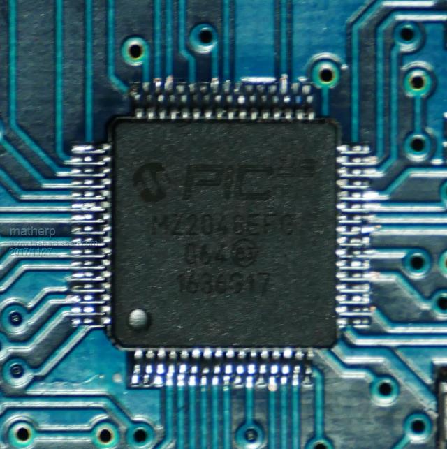 |
||||
| Grogster Admin Group Joined: 31/12/2012 Location: New ZealandPosts: 9931 |
OK, I stand corrected.  Note I said 'Generally speaking'.....  I do like my QFP pins up close and personal though for easy soldering, but that admittedly, is just me. Smoke makes things work. When the smoke gets out, it stops! |
||||
| djuqa Guru Joined: 23/11/2011 Location: AustraliaPosts: 447 |
My cat suffered the most, I yelled at him several times. I can/ have got over it already. Thanks for the offer, 1 is totally cactus, the other is in the too hard basket until sometime in the future. I may just buy a pre-assembled module from you instead Yes, I wanted to try some of the clever features that MBasic 4.5 on my duinomites/Maximite doesn't have. The 2 kits came from SiliconChip and all 3 PIC32s were supposedly supplied preprogrammed. They charged $15 for the 3rd (the replacement one). Don't get me wrong. I think the MicroMite is a great concept, just the frustration level of trying to make it was 11+. I love my collection of 10+ Duinomites. Sad thing is I used to rework SMD based board's for MAJOR computer company as my fulltime JOB PostScript Just ordered 2 preassembled Explore28 modules from RichTech NZ to satisfy my MM+ cravings. VK4MU MicroController Units |
||||
palcal Guru Joined: 12/10/2011 Location: AustraliaPosts: 2039 |
E-28 modules won't do MM+ you need the 64 or 100 pinners to do that. Paul. "It is better to be ignorant and ask a stupid question than to be plain Stupid and not ask at all" |
||||
| djuqa Guru Joined: 23/11/2011 Location: AustraliaPosts: 447 |
DOH! as long as I can run MMBasic I will be happy. Spent enogh time, money, effort on them already. ARDUINO clones and my reflashed duinomites are my main focus now. A 5$ Arduino NANO or $7 Wemos D1 can do a lot of what most people need. VK4MU MicroController Units |
||||
Azure Guru Joined: 09/11/2017 Location: AustraliaPosts: 446 |
The 28 pin units are normally through hole, so they would be much easier to hand assemble. They do cover a most of the Silicon Chip based Projects. My previous and some current work also includes repairing faulty PCB's or assembly PCB's. There is a difference between hand assembling an SMD PCB and repairing an already assembled SMD PCB where components are already in place. I find you need to take your time and individually solder each component, not in batches like we tend to do on PTH assembly. If you have a reflow oven, then that makes it easier on the soldering, but you still need to take time applying solder paste and placing components since you most likely wont have a PCB Paste stencil for these projects. I use a mixture of fine tipped iron and SMD Hot air nozzle depending on the components. I usually solder without magnifying (many many years of practice) and then check for dry/bridge joints with magnifier and do cleanup. I am only new to actually playing with the MM's and they are great. Don't give up, go back to the bad ones you have when you are relaxed and consider them as more practice and a repair job wrapped into one PCB :) |
||||
| Grogster Admin Group Joined: 31/12/2012 Location: New ZealandPosts: 9931 |
Yes, the Silicon Chip - chips would have been pre-programmed, so you can ignore that part of my statement. I thought you had actually got them from me anyway. EDIT: The E28's can still do the SPI LCD screens and most of the core of MMBASIC features. They just can't do the fancy MM+ GUI controls. You can still use touch controls on the E28 though, but the MM+ has better looking GUI controls. Smoke makes things work. When the smoke gets out, it stops! |
||||
bigmik Guru Joined: 20/06/2011 Location: AustraliaPosts: 2979 |
GDay David, Same offer as Grogster.. If you want to send them to me I will see what I can do to fix one/both for you. Kind Regards, Mick Mick's uMite Stuff can be found >>> HERE (Kindly hosted by Dontronics) <<< |
||||
| djuqa Guru Joined: 23/11/2011 Location: AustraliaPosts: 447 |
thanks for the all offers, but my fault, my &&###, my fixup VK4MU MicroController Units |
||||
| Phil23 Guru Joined: 27/03/2016 Location: AustraliaPosts: 1667 |
Not taking away from the E64; I've got aa couple.... But the CGMicroBoard2 is not a bad option either. Have a couple of them; 2.8" displays piggy backed on one side, and an Arduino Proto board sitting on the other. Made it pretty easy to knock up 2 simple projects. Phil |
||||
| Warpspeed Guru Joined: 09/08/2007 Location: AustraliaPosts: 4406 |
I am getting pretty ancient too, and my eyesight is getting steadily worse, I try to avoid the really fine pitch packages and stick with the larger through hole parts and now use sockets for all my ICs. But there is a bit of a trick to soldering fine pitch packages. I agree, solder paste is probably not the best technique for do it yourself fine pitch components at home. Much better is to initially flood all the pins with resin cored solder, and then use solder wick to remove the surplus solder. If you remove too much, its easy enough to put some back. But with a bit of practice, its possible to very quickly make some pretty lean joints leaving minimum solder remaining. Just enough to see on each pin without any possibility of solder bridges. If you have fifty pins per side (or whatever) just run down each side with big solder and a big tip. Its not necessary to solder each pin individually ! Then run down each side with solder wick sucking up the excess. In just a few seconds its possible to have fifty very neatly soldered pins sitting in a morass of surplus flux. I think that is probably the secret. The solder wick is saturated with flux and leaves a nice shiny solder fillet, as long as you don't remove too much solder. Cheers, ĀTony. |
||||
| Grogster Admin Group Joined: 31/12/2012 Location: New ZealandPosts: 9931 |
I agree with Warpspeed here.  I will see if I can find my camera that came with my microscope, and capture a video of how I do my chips. Solder paste is good if you have a stencil and a reflow oven. I don't like it for manual soldering with an iron. IMHO, you are far better off with fine solder, and some decent flux. I have had issues in the past with the "Flooding" method, where you just add a whole heap of solder to all the pins and short them all out in a big line of molten solder. Wicking the excess solder out from between the pins can be a real problem with fine-pin-pitch stuff, as the surface tension can sometimes make tiny little solder hairs stay BEHIND the pins where you can't get at them with the wick. This again, is just MY thoughts on it, and certainly not raining on the parade of those who like that method. Smoke makes things work. When the smoke gets out, it stops! |
||||
| djuqa Guru Joined: 23/11/2011 Location: AustraliaPosts: 447 |
No, I have gone totally over to the dark side. Arduino Clones ( Pro Mini, Nano, UNo, Mega2560) and these amazing little CHEAP ($18AUD for 5) NodeMCU/arduino compatible esp8266 based boards  VK4MU MicroController Units |
||||
| Warpspeed Guru Joined: 09/08/2007 Location: AustraliaPosts: 4406 |
Another somewhat controversial trick involves precise positioning of the chip over the pads. Success in soldering requires the pins to be very precisely centered over the pads, and that is not so easy to do. A very small spot of your favorite glue under the chip will allow you to move the chip around with maybe a pin or a needle under your microscope until its exactly in position. Then go away for a while and allow the glue to set. The chip should then not move if a few corner pins are then very delicately soldered first. Old age brings us patience, as well as sometimes poor vision and/or the shakes! So its a bit of an old fart's trick that the young guys laugh at. But it does help a lot. Its not necessary to bury the chip in high strength epoxy, just a small spot of something less permanent that can easily be prised apart later if necessary. Cheers, ĀTony. |
||||
| Azure Guru Joined: 09/11/2017 Location: AustraliaPosts: 446 |
I remember back in the day when I was involved in mass PCB production. For SMD parts they used to use a tiny droplet of something like a locktite before placing the components. Held part in place but could still be removed for repair/rework later if needed. |
||||
| Page 1 of 2 |
|||||
| The Back Shed's forum code is written, and hosted, in Australia. | © JAQ Software 2026 |
