Notice. New forum software under development. It's going to miss a few functions and look a bit ugly for a while, but I'm working on it full time now as the old forum was too unstable. Couple days, all good. If you notice any issues, please contact me.
OA47 Guru Joined: 11/04/2012 Location: AustraliaPosts: 1044
Posted: 04:46am 30 Nov 2017
Copy link to clipboard
Print this post
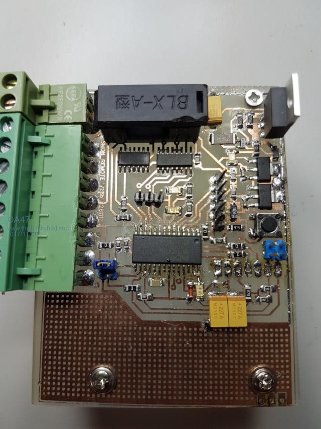
I need some suggestions of what to try next. I have a project PCB (home made single sided) one of the 5 I have made refuses to communicate thru the Console port. I initially went through a fairly thorough check of all of the solder joints and found no issues. I have continuity tested the tracks from the console pins to the chip and tested for shorts from either track. In desperation I have removed the radio unit and replaced the Micromite chip, re-programmed it and can see it boot into the program (Autorun is on). I am using a USB-Serial converter and I can see the LEDs on it flash when I try to communicate with the chip. The PC, USB-Serial and cables work fine on another unit so I am at a loss as to what to try next. Wondering if any shedders have had similar problem that they may have solved? I will post a photo of the unit just in case there is a blindingly obvious error in my construction Please forgive the condion of the PCB/soldering as many components have been removed and replaced
.
OA47
Grogster Admin Group Joined: 31/12/2012 Location: New ZealandPosts: 9931
Posted: 05:46am 30 Nov 2017
Copy link to clipboard
Print this post
Usually the console 'Just works'.....
I DID run into this kind of issue yesterday with an old project that flatly refused to talk on the console, no matter what.
I fixed that by reflashing the firmware into the chip - then it DID respond. You say you have reprogrammed the chip. Can you clarify if you just reloaded the BAS file to the MM, or you reflashed the MMBASIC HEX file to the chip.Smoke makes things work. When the smoke gets out, it stops!
OA47 Guru Joined: 11/04/2012 Location: AustraliaPosts: 1044
Posted: 05:51am 30 Nov 2017
Copy link to clipboard
Print this post
Gday Grogs, the .hex file I used is a complete copy of data, MMbasic, Libraries, CFunctions, Options and basic program. the only thing that changes between units is an ID number in VAR SAVE.
Out of desperation I just flashed a 28pin DIL chip with the same .hex file and it talks ok
OA47Edited by OA47 2017-12-01
Grogster Admin Group Joined: 31/12/2012 Location: New ZealandPosts: 9931
Posted: 05:56am 30 Nov 2017
Copy link to clipboard
Print this post
OK. Reflash the standard MMBASIC HEX back into your board - just for the purposes of testing - and see if that gives you the console back.
If it does, then something in the HEX you are programming is causing the issue.
Make sure that when you read the PIC32 with IPE to then export the HEX, that you are reading BOTH the boot memory, and the program memory - you set this in the IPE advanced options.Smoke makes things work. When the smoke gets out, it stops!
Grogster Admin Group Joined: 31/12/2012 Location: New ZealandPosts: 9931
Posted: 05:59am 30 Nov 2017
Copy link to clipboard
Print this post
Well now, that is very interesting. By all accounts it should indeed be working just fine.....
Do you have a logic analyser? Smoke makes things work. When the smoke gets out, it stops!
OA47 Guru Joined: 11/04/2012 Location: AustraliaPosts: 1044
Posted: 06:08am 30 Nov 2017
Copy link to clipboard
Print this post
Grogs, as suggested, I re-flashed the unit with a bare MMBasic 5.04.05.hex file and reset the teraterm back to 38400 baud but still no talkies.
OA47 Guru Joined: 11/04/2012 Location: AustraliaPosts: 1044
Posted: 06:12am 30 Nov 2017
Copy link to clipboard
Print this post
Unfortunately I don't have a Logic Analyser in the kit. I am wondering if changing the Vcap may have some effect. I haven't done it as yet as the unit was autorunning and my past experience with bad Vcaps showed that the Micromite wouldn't boot.
Grogster Admin Group Joined: 31/12/2012 Location: New ZealandPosts: 9931
Posted: 06:15am 30 Nov 2017
Copy link to clipboard
Print this post
OK, no talkies with standard MMBASIC suggests a problem with the connection to the console pins.
I know you have replaced the chip and done some continuity testing. Did that testing involve testing RIGHT FROM THE PIN to the header, and NOT just the solder by the pin?
I am wondering if you need to reflow your solder around the console pins to be totally sure they are actually making contact to the header pins.
Rather mysterious..... Smoke makes things work. When the smoke gets out, it stops!
OA47 Guru Joined: 11/04/2012 Location: AustraliaPosts: 1044
Posted: 06:31am 30 Nov 2017
Copy link to clipboard
Print this post
Changed the 10UF X5R Vcap with a 47U Tant but no difference. Got out the multimeter again and less than 1 ohm between the gold plated pin and each of the PIC pins. I checked these measurements with another working unit.
Interestingly I get around 19K from pin 11 OR 12 to gnd on a working unit but on the faulty unit I get 19K to gnd on 12 but 10k on pin 11. will investigate further.Edited by OA47 2017-12-01
OA47 Guru Joined: 11/04/2012 Location: AustraliaPosts: 1044
Posted: 06:50am 30 Nov 2017
Copy link to clipboard
Print this post
Hooray!!!!!!!!!!!!!!
Thanks again for your help Grogs. There is a track that goes between the GND pin and the Console PIN 11 pin and there was a small solder blob living under the plastic base of the headers removed the plastic base and all is well in the land of the Micromites.
Azure Guru Joined: 09/11/2017 Location: AustraliaPosts: 446
Posted: 08:21am 30 Nov 2017
Copy link to clipboard
Print this post
Nicely done, I was going to suggest a quick wash and brush with some ISO or FLuxclean can sometimes do amazing things.
Nice work for home made PCB.
OA47 Guru Joined: 11/04/2012 Location: AustraliaPosts: 1044
Posted: 08:40am 30 Nov 2017
Copy link to clipboard
Print this post
Thankyou Azure. The other units do look a lot more presentable as I haven't replaced most of the components 2 or three times
Alastair Senior Member Joined: 03/04/2017 Location: AustraliaPosts: 161
Posted: 09:11pm 30 Nov 2017
Copy link to clipboard
Print this post
@OA47 what system do you use to produce your PCBs ? Yours look quite sharp with good edges so is it a laser printed mask of some sort?
I used to make them myself many years ago but hated the messy process. Is there a better way nowadays?
For real projects I have the boards made in China but do find for projects that are too complex for vero etc, the delay in getting them, plus the cost of freight for a small one off job very frustrating. Cheers, Alastair
Grogster Admin Group Joined: 31/12/2012 Location: New ZealandPosts: 9931
Posted: 09:25pm 30 Nov 2017
Copy link to clipboard
Print this post
Great.
That one was quite bizarre.Smoke makes things work. When the smoke gets out, it stops!
OA47 Guru Joined: 11/04/2012 Location: AustraliaPosts: 1044
Posted: 10:05pm 30 Nov 2017
Copy link to clipboard
Print this post
For prototype and quick jobs I use the Press and Peel process to make the boards. This method has been much more successful since I started using the hand held laser temperature meter to set the temperature on the dis-guarded electric iron. I have tried to use as much SMD as possible to minimise drilling. You may notice that meant using a half a dozen 0 ohm resistors to keep the design single sided.