
|
|
Forum Index : Microcontroller and PC projects : Transistor bases in parallel....
| Page 1 of 2 |
|||||
| Author | Message | ||||
Grogster Admin Group Joined: 31/12/2012 Location: New ZealandPosts: 9931 |
Hi folks.  I just want to run something past the members. I have an I/O pin currently driving a relay, but would like to add a 2nd relay to that same output, to switch something else at the same time. I am planning to connect both driver transistors' base connection together, as I have seen this done before in the past, but I myself have never done it. Left up to me, I would have the 2nd transistor base go via it's own resistor back to the I/O pin, but to save me having to route another track and install another resistor, I am just curious..... Here is how I plan to do it: 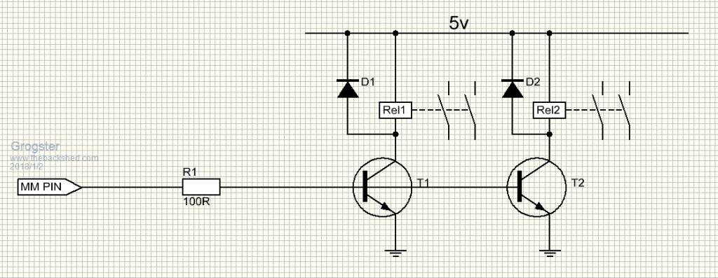 Thoughts? Does anyone have any major issues with that idea? Smoke makes things work. When the smoke gets out, it stops! |
||||
| CaptainBoing Guru Joined: 07/09/2016 Location: United KingdomPosts: 2171 |
I would go with the second resistor too. The two transistors won't be identical and you might find one will "run away" with all the current... then again you might find it is fine. To be certain each would get it's own resistor and separate link to the pin. FETs would be nice and you could certainly drive them like this (and no inline resistor). BS170 or 2N7000 should be OK - max Vgs of 3V and Ids of 500mA/200mA continuous. You could drive them directly from the pin but I recommend a 47K pull down on the gates to avoid any rogue switching in the eye-twinkle between start-up and you configuring the pin. I have used both direct on pins and had zero problems even though the 3.3V is a bit near to the Vgs. Both are older parts but huge pools of old new stock exist = cheap, cheap, cheap! |
||||
Azure Guru Joined: 09/11/2017 Location: AustraliaPosts: 446 |
If you are trying to take short cuts and make it quick and nasty you could wire both relays to one driver transistor if they are just doing a low duty cycle on/off (each with a back EMF diode across them) as long as the transistor can safely drive both relays. Not very elegant though, would recommend the more failsafe independent resistor/transistor drivers like you yourself and Captian Boing suggested. |
||||
OA47 Guru Joined: 11/04/2012 Location: AustraliaPosts: 1044 |
ULN2001 is always my friend.  Happy New Year Grogs. (Even if you have had it longer than us Aussies) |
||||
| Turbo46 Guru Joined: 24/12/2017 Location: AustraliaPosts: 1685 |
Definitely two resistors for the reason CaptainBoing stated. Also the resistor value seems low, it will attempt to draw 27mA from the micromite pin! (3.3-0.6)/100 = 0.027. I suggest 330ohm for one transistor and 680ohm for two transistors. With a 680ohm base resistor a transistor with an Hfe of 50 could drive a relay requiring 200mA. Bill Keep safe. Live long and prosper. |
||||
| Grogster Admin Group Joined: 31/12/2012 Location: New ZealandPosts: 9931 |
Thanks guys. I will route the extra track - will only take ten mins or so.(board is big) I see parallel bases on transistors in schematics on the web, and even in PDF's etc. Perhaps THOSE transistors are a matched set or something? My question has been answered in any case, so thanks chums. @ OA47 - Yes, I have used the 2003A(I think) before. Perhaps..... @ Turbo46 - Yes, quite right. 100R was typo. It is indeed a 330R on the board. Transistors are BC337's, which I think are Darlington anyway, so would only need a tiny base current.  Perhaps 1k? Perhaps 1k?EDIT: No, the 337 is just a standard 500mA single NPN. Not Darlington. Must have been thinking of something else.... EDIT: Done. That did not take as long as I thought. Smoke makes things work. When the smoke gets out, it stops! |
||||
bigmik Guru Joined: 20/06/2011 Location: AustraliaPosts: 2979 |
Grogs, As CapnBong mentioned you should use a second resistor.. you could of course change the relay for one that has more poles.. so it is effectively 2 relays (or more) in one. Kind Regards, Mick Mick's uMite Stuff can be found >>> HERE (Kindly hosted by Dontronics) <<< |
||||
palcal Guru Joined: 12/10/2011 Location: AustraliaPosts: 2039 |
If the relay is easily changed use a double pole relay. Paul. "It is better to be ignorant and ask a stupid question than to be plain Stupid and not ask at all" |
||||
redrok Senior Member Joined: 15/09/2014 Location: United StatesPosts: 209 |
Hi Grogster; Bipolar transistors are never operated with parallel bases in the way you are suggesting. There are a couple of exceptions: 1. The transistors are precisely matched and thermally connected. 2. Bases may be paralleled but there needs to be emitter resisters to balance the base currents. This is commonly done in current mirror circuits. Are you sure that you can't drive the 2 relays from a single transistor? If not, find a transistor in the same package with a higher current rating. A better solution would be to replace the 2 bipolar transistors with an N-Chanel MOSFET. The BEST solution is to drive the 2 relays with 1 MOSFET. Now you probably don't need the resistor at all and you only need 1 snubber diode. It's a win all around. redrok |
||||
| Grogster Admin Group Joined: 31/12/2012 Location: New ZealandPosts: 9931 |
Perhaps I should clarify at this point - the relays are Panasonic latching relays, with a single coil. You have to reverse the current flow through the coil to make it latch the other way. This is done with two transistors and a couple of 47R resistors: 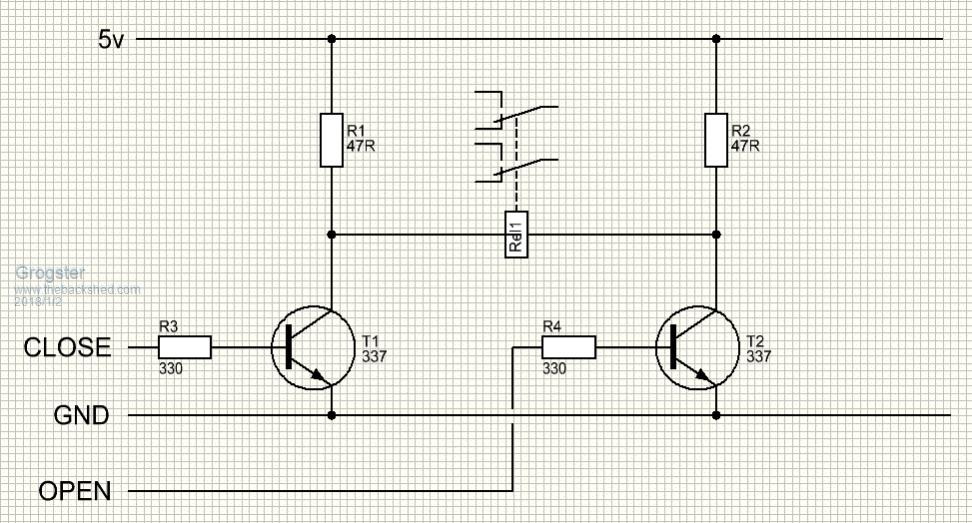 Perhaps I can parallel up the relay coils in this arrangement, but figured a separate driver for each relay would be better design practise. I guess paralleling the relay coils would work on the same circuit when I think some more about it. Thoughts? The OPEN and CLOSE pulses from the MM are only 10mS in duration - just enough to trip the latch. The latches are 4.5v coil, so are perfect on a 5v supply less 0.6v or so loss across the transistor. Smoke makes things work. When the smoke gets out, it stops! |
||||
| Turbo46 Guru Joined: 24/12/2017 Location: AustraliaPosts: 1685 |
I think you will need reverse biased diodes across the transistors and the 47ohm resistors. Have you considered an H-Bridge IC? Edit LB1938FA for example. Keep safe. Live long and prosper. |
||||
| Grogster Admin Group Joined: 31/12/2012 Location: New ZealandPosts: 9931 |
Hi Turbo. Re: Back EMF diodes - Nope, you don't.  This was discussed in detail in this thread from 2015 This was discussed in detail in this thread from 2015NORMALLY, you would definitely need them, but the way this circuit is arranged makes them unnecessary. Please check out the other thread for all the details, mathematics, and technical reasons why this is the case here. Smoke makes things work. When the smoke gets out, it stops! |
||||
| Turbo46 Guru Joined: 24/12/2017 Location: AustraliaPosts: 1685 |
Thanks Grogster, you are right, I see that an H-Bridge is mentioned there also. I would suggest that the positive side of the two 47ohm resistors be taken to an 'island' pad and then that pad connected via a single track to the +5volt supply. Doing that would keep circulating currents from affecting the supply. Bill Keep safe. Live long and prosper. |
||||
goc30 Guru Joined: 12/04/2017 Location: FrancePosts: 435 |
hi you can see more info here https://electrosome.com/interfacing-relay-with-pic-microcontroller/ i suggest to use an ULN2803A as driver for relay. In this case, you can drive each relay you can also put a PCF8574 between proc and driver. In this case, you can drive your relays in I2C bus and free digitals pins |
||||
| redrok Senior Member Joined: 15/09/2014 Location: United StatesPosts: 209 |
Hi Grogster: Here is another driver concept circuit snippet: 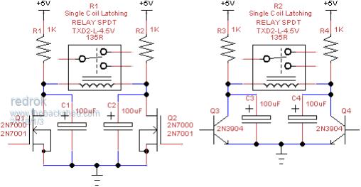 These circuits eliminate a couple of problems that have been discussed. 1. There is essentially no disturbance of the power supply so no large filtering cap is needed. 2. The capacitors snub the inductive kickback voltage so no diodes are required. 3. There is no chance of harm to the transistors nor the relay if, by mistake, one or both are left in the ON state. 4. The capacitor charging resistors are much higher in value than the 47R in the other circuit resulting in less energy consumed for each switching event. There are a couple of usage restriction: 1. The transistors need to be turned ON quickly. But since they are controlled by a micro that would be no problem. 2. There must be a delay from when one transistor is turned off and activating the other. In my example the RC time constant is about 0.1S, (1K * 100uF). So 5 time constants or 0.5S is sufficient time before activating the other transistor. I didn't try to find out what the minimum transistor OFF time was. I tested this with a different relay, TX2SA-L2-5V. This is a 2 coil latching relay which is a close cousin to the TXD2-L-4.5V I think you are using. I tested the circuit using only 1 of the coils. The coil resistance is about the same between the two relays. I found that 33uF would work but 10uF didn't. For safety I chose 100uF. In any case, the delay time from turning ON the transistor and the contacts switching was about 2.5mS. I also tried using 100K resistance which worked fine but the 5RC time was about 40S or so. I'll leave the transistor biasing up to you. The only requirement is to get the transistors turned on sufficiently to quickly discharge the capacitor and drive the relay. Have fun!!! redrok AD0TJ I just tried running this circuit on 12V with the 5V relay. I changed the capacitor to 10uF. And the relay switched on in about 1mS instead of the 2.5mS when on 5V. Cool huh!!! You can do this because there is a limited amount of energy stored in the capacitor. I made a test program and have switched the relay over 5000 times. I can see no detrimental problems. The relay feels cool to the touch. |
||||
| Grogster Admin Group Joined: 31/12/2012 Location: New ZealandPosts: 9931 |
Hi. Using the NPN circuit on the right of your image, how does the C-E path in the transistor survive you shorting out the cap across it when you switch that transistor on? I would have thought the short-circuit current of the 100uF cap could kill the transistor by cooking it's C-E path? In any event, I expect these caps are to be standard aluminium electro's? I have read that tantalums intently dislike being short-circuited like that. I believe you as you have done the testing, but I am just curious. Do you think I could put two relay coils on the one circuit? That would save me two PCB traces, two resistors, and two transistors if I can parallel up the relay coils and drive them both from the one circuit if you see what I mean. Smoke makes things work. When the smoke gets out, it stops! |
||||
| redrok Senior Member Joined: 15/09/2014 Location: United StatesPosts: 209 |
Hi Grogster;The 2N3904 has a continuous current rating of 200mA. However, this operation is not continuous. Its just a short pulse. You can't "Cook" it because the total energy content stored in the 100uF capacitor is: C * V^2 / 2 = Charge in WattSeconds 100uF * 5V^2 / 2 = 0.00125WS (or 1/800th of a WattSecond) This is quite a small charge of energy to be converter to heat. Sure, if the transistor had to discharge this amount of energy 800 times per second continuously it would be dissipating 1 Watt of power. But this can't happen because the average power dissipation is limited by the capacitor charging resistors. BTW, the energy in the other capacitor is dissipated in the relay's coil resistance. Yes, that was what I used. Although, when I tested this circuit on 12V I used 10uF ceramics. In any event the maximum current would be limited to the base current times the gain. At high currents the gain is usually quite poor so is self limiting. I suppose 240 to 1K base resistance is suitable.That may be true if there was a "True" short circuiting of the Tantalum capacitor. However, the maximum current capability of small signal transistors are quite limited. Now if a power MOSFET with milliOhm on resistance was used there could be a problem. Short circuiting failure in Tantalums is caused by microscopic fusing of the metalization in the capacitor structure. This can happen because the internal resistance of Tantalums is so low. But a signal transistor is not really capable of such high currents. I would suggest using the aluminum caps in this application. I am confident you can do this. The question is not can the transistor drive 2 coils, because they can. The actual question is "is there enough charge in the second capacitor to switch 2 relays"? I found that 33uF worked with my relay reliably. I just suggested using 100uF because I was designing very conservatively. I think 100uF will work fine. Just make sure your pads could accommodate a bit larger capacitor, you know, just in case it's needed.I wish you would consider using MOSFETs instead of bipolars. In this case, this would eliminate the base resistors. Also, unlike many application where MOSFETs are use you don't need the gate pulldown resistor. There is no harm if the MOSFET gate floated up partially turning it on as the 1K charge resistors limit the current. Rant Mode ON: I haven't used bipolars in my designs for many years. MOSFETs tend to be superior in almost every way. Lower on resistance, lower on voltage, fewer parts in the circuit, dissipate less power so don't get as hot, and less loading of the microprocessor pin. Rant Mode OFF: Have fun with this specialized small relay driver. redrok |
||||
djuqa Guru Joined: 23/11/2011 Location: AustraliaPosts: 447 |
Mosfets are preferable for the task you propose. Exactly what have you got against using them. Drive current is more than enough to drive 2 relays VK4MU MicroController Units |
||||
| Grogster Admin Group Joined: 31/12/2012 Location: New ZealandPosts: 9931 |
@ redrok: Thanks a bunch for all that information. That has cleared it up for me. @ redrok AND djuqa: I have nothing at all against MOSFET's. The problem is that when I did my electronic theory, everything was done using NPN or PNP transistors, and MOSFETS were only in the really expensive stuff. Now, of course, MOSFET's are everywhere, but as it is unfamiliar turf to me...... I know a transistor-based approach will work, but not having enough practical experience with MOSFET's makes me unwilling to use them from fear that they won't work, or that I will hurt them as the gate on most is very sensitive to static etc.It's probably just me being a little stubborn, I guess! Smoke makes things work. When the smoke gets out, it stops! |
||||
| djuqa Guru Joined: 23/11/2011 Location: AustraliaPosts: 447 |
When I did my initial Electronic theory BC108's were considered new devices, valves were still popular and ICs were extremely rare. Didn't stop me stretching my knowledge. I bet when you first studied electronics PIC/ATMEL microcontrollers were also were rare and expensive. MOSFETS are a lot more robust than most give them credit for. After all all those nice little chips you like using are FULL of them. Not many IC devices utilise Bipolar Transistors. VK4MU MicroController Units |
||||
| Page 1 of 2 |
|||||
| The Back Shed's forum code is written, and hosted, in Australia. | © JAQ Software 2026 |
