
|
|
Forum Index : Microcontroller and PC projects : MMX Help needed
| Page 1 of 3 |
|||||
| Author | Message | ||||
OA47 Guru Joined: 11/04/2012 Location: AustraliaPosts: 1044 |
A few days ago I loaded a 144 pin MMX board mostly with components I had on hand and what I could purchase locally. Although I am still waiting to receive some components such as the SD card socket and audio socket I thought that I had loaded enough components to program the unit. I have not loaded the PIC16F1455 as I thought I could program with the PICKit 3 I have. The problem I have is that the MPLAB IPE 3.50 does not connect to the chip. Here's what I checked: Checked 5V rail OK Checked 3V3 rail OK Checked MCLR at high and reset pulls low and connects to pin 1 ICSP Checked with CRO OSC is working on pin71 Checked Ground on pins 17,32,54,63,75,89,108,123,136 and 42 (AVSS) and connects pin 3 ICSP Checked 3V3 on pins 18,33,55,64,88,107,122,137 and 74 (VUSB3V3)and connects pin 2 ICSP Checked connection of PGD to pin 38 and connects pin 4 ICSP Checked connection of PGC to pin 37 and connects pin 5 ICSP I have tried powering the chip from the PICKit 3 as well as locally I am at a loss to think of what else to check. Hope someone has some ideas. OA47 |
||||
disco4now Guru Joined: 18/12/2014 Location: AustraliaPosts: 1109 |
Do you need a 10ohm resistor to get AVDD connected? F4 H7FotSF4xGT |
||||
| WhiteWizzard Guru Joined: 05/04/2013 Location: United KingdomPosts: 2962 |
@OA47 Ensure you have the inductor (near top-right of main PIC). Also 10K to the right of the smaller PIC. And the crystal oscillator along with the HeartBeat LED (and 330R) will give visual feedback that all programmed ok (obviously once your PicKit3 can see it). Need to ensure no PIC pins bridges too  |
||||
| OA47 Guru Joined: 11/04/2012 Location: AustraliaPosts: 1044 |
@Disco4Now. I have a choke (L1) between AVDD and 3v3 as per "Micromite eXtreme Manual" page 8. OA47 |
||||
| OA47 Guru Joined: 11/04/2012 Location: AustraliaPosts: 1044 |
@WW. Thankyou for your advice. I have checked continuity from 3v3 thru L1 and to pin 41 is ok. The 10K resistor (R18) is there. Have checked the OSC is functioning with the CRO. Heartbeat LED is installed and have just had another check for bridged pins. OA47 |
||||
| WhiteWizzard Guru Joined: 05/04/2013 Location: United KingdomPosts: 2962 |
The one other 'gotcha' is the 22uF cap on the underside - bet you possibly missed that one!  |
||||
| matherp Guru Joined: 11/12/2012 Location: United KingdomPosts: 11144 |
You don't need anything except the power supplies to the chip and a bit of decoupling to program with a pickit (always use an external supply). Even the oscillator doesn't need to work and it will still program OK. You have got pin-1 in the correct place (just checking) Is R18 the correct value (10K) - too low and it will overpower the pickit Have you got any other ready-built MMX boards you can test the pickit on? Did the pickit load the correct firmware into itself? Have you pereviously used the pickit in pickit2 mode - if so it needs resetting Which variant of the PIC32 are you using? If you have another PCB and another chip just solder a couple of caps on the PCB, R18, L1 and the ISCP header. You can then just locate the PIC without soldering, press down and hold firmly and it should program |
||||
| OA47 Guru Joined: 11/04/2012 Location: AustraliaPosts: 1044 |
@WW I have heaps of 10uF XR5 caps I use on the MM's so I was able to place two of the side by side under the PCB. |
||||
| matherp Guru Joined: 11/12/2012 Location: United KingdomPosts: 11144 |
The chip will program and run fine without the 22uF. It is really just there for belt and braces |
||||
| OA47 Guru Joined: 11/04/2012 Location: AustraliaPosts: 1044 |
@ matherp. I do have other 144 pin pcb's but I don't have any spare 144 pin chips at the moment. Alternately I have some 100 pin chips but as yet don't have the boards for them. (I had received some 100 pin boards from Grogster some time back and diligently installed a 100 pin 2048 chip only to realise that the boards supported the 470 chips.) Murphies Law Definitely have the chip in the right orientation. Not exactly sure of your question here. When I selected the MZ chip in the software, it downloaded info for that chip but I didn't change any settings that I had been using on the 170 chips that I had been flashing other than the chip type and the .hex file |
||||
| WhiteWizzard Guru Joined: 05/04/2013 Location: United KingdomPosts: 2962 |
@OA47 Could you take a hi-res photo of your PCB and post/email it? Possibly 'other eyes' may help spot something! |
||||
| matherp Guru Joined: 11/12/2012 Location: United KingdomPosts: 11144 |
Also can you measure current draw for the PCB. I get 190mA with a 9V supply for a fully populated PCB |
||||
| OA47 Guru Joined: 11/04/2012 Location: AustraliaPosts: 1044 |
The board is drawing around 50mA at 10V input. I will try to post a link to a high res photo of the board and hopefully something will show up that I have done in error. |
||||
| OA47 Guru Joined: 11/04/2012 Location: AustraliaPosts: 1044 |
Here are links (hopefully) to a couple of shots of the board I have loaded: 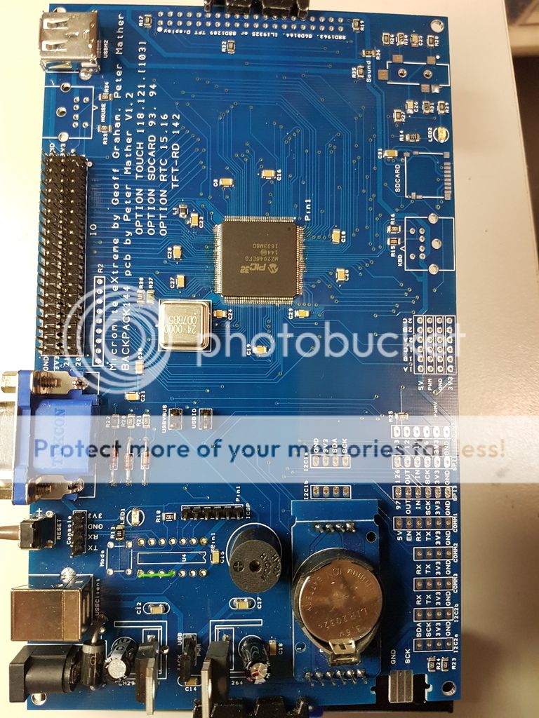 Full board picture[/URL] 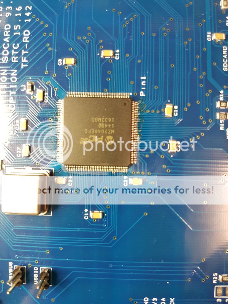 PIC Chip as close as I can get in focus[/URL] I am sure that I have done something silly and hope it will be blatently obvious to someone else. OA47 |
||||
| WhiteWizzard Guru Joined: 05/04/2013 Location: United KingdomPosts: 2962 |
@OA47 Just woke up and seen your photos. My initial observation is that the OSC unit is 180 deg out. I need to go check cos it does look like you have Pin1 in silk screen oriented to your OSC module - but I am 99.9% certain I mount it the other way. Let me go check after I have downed a coffee to wake me up WW |
||||
| WhiteWizzard Guru Joined: 05/04/2013 Location: United KingdomPosts: 2962 |
Yep - Pin1 of the OSC module should be top left IF this is the same design as Peters MMX144 PCB (without any modifications). Check this thread (scroll down a little) to see the photo of an unpopulated PCB showing Pin1 in top left (i.e. nearest to the 3x 120R VGA resistors). Swap that around (if an unmodified PCB) and try again Leads to question - why does silkscreen show different on your PCB?  |
||||
| WhiteWizzard Guru Joined: 05/04/2013 Location: United KingdomPosts: 2962 |
I see the circuitry around the OSC module IS positioned differently so my two above posts are probably irrelevant. I do not have that design of MMX144 so apologies for mis-information there! EDIT - I did say that I'd just woken up!! |
||||
| WhiteWizzard Guru Joined: 05/04/2013 Location: United KingdomPosts: 2962 |
Is the green wire on PIC1455 Pin 11 just a 3v3 'check-point'? OR is it linking to Pin8 for some reason? This shouldn't have an affect (assuming the PIC1455 circuit is different to mine too!). It is just curiosity. |
||||
| WhiteWizzard Guru Joined: 05/04/2013 Location: United KingdomPosts: 2962 |
|
||||
| OA47 Guru Joined: 11/04/2012 Location: AustraliaPosts: 1044 |
WW, The boards I have are Version 1.2 not Version 1.1 as your post links to, so I think that would be the difference with the oscillator. As I hadn't populated the PIC1455 I used the green link to make LED1 a 3V3 power LED. Good morning and welcome to Monday. (A Labour Day Holiday here in my state of Australia) OA47 |
||||
| Page 1 of 3 |
|||||
| The Back Shed's forum code is written, and hosted, in Australia. | © JAQ Software 2026 |
