
|
|
Forum Index : Microcontroller and PC projects : Nixie Tube Driver
| Author | Message | ||||
redrok Senior Member Joined: 15/09/2014 Location: United StatesPosts: 209 |
Hi All; I've got the bug to make a Nixie Clock. I've been experimenting with a "Minimalist" driver circuit. 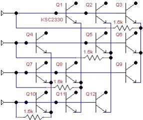 1. It uses an array of up to 12 KSC2330 high voltage NPN transistors. Their rated at 300V. 2. The circuit operates in a Cathode Current Sink arrangement. The current is about 2.5mA when driven at 3.3V from 4 uMITE pins and controlled by 4 1.6kθ emitter resistors. It is controlled by only 4 connections. 3. The circuit looks simple but it's not. The way it operates is 2 pins Must be set as Outputs, 1 High and the other Low. The other 2 pins Must be set as Inputs. There are 12 combinations which select only 1 KSC2330 to act as the current sink, the others are Off. There is also a 13th combination in which All the Pins are set as Inputs which Blanks out the Nixie. When first testing the circuit I was very cautious about leakage currents from the 180V supply passing back through the uMITE pins causing damage so I added 4 clamp diodes up to 3.3V. The KSC2330 spec says the worst case leakage current can be as high as 0.1�A at 25�C. The spec is a bit light so doesn't tell me what the current will be at high temperatures, but should be less than 25�A or so. However, the power dissipated in the transistors is quite low so I don't think they will get very warm. I got a little braver and measured the current gathered by the 4 clamp diodes and saw none. So I removed the clamp diodes. Works perfectly. I cranked the supply up to 300V without diodes. Still OK. I haven't tried higher voltage yet. I'm using old Russian Nixies which say the cutoff voltage is about 120V so the transistors don't see more than 180V or so. Now the question! In discussions about protection circuits I think it was said there are no protection diodes to Vcc. Is this correct? If so, am I safe is in allowing 0.3�A, (leakage from 3 transistors), pushing back into the pin when set as inputs? I really don't want to use the extra diodes, this would detract from the Minimalist theme if I can. For a 6 digit clock that would be 24 extra diodes. Any suggestions? redrok |
||||
| Geoffg Guru Joined: 06/06/2011 Location: AustraliaPosts: 3353 |
The pin input/output circuit in the PIC32 is not as simple as just a couple of diodes clamping the input to Vss and Vdd. Some time ago I ran a series of tests where I applied 5V to a 3.3V input pin. In that case you would expect the pin to draw a current if simple clamping diodes were present - but the current was negligible (a few uA). As a result I now use external clamping diodes, at least that guarantees that the input voltage remains in spec. If you have a DMM with a high input impedance (ie, 1000M) you could just measure the voltage on the pin. Geoff Graham - http://geoffg.net |
||||
| JohnS Guru Joined: 18/11/2011 Location: United KingdomPosts: 4298 |
Sorry to raise this, but sooner or later something "bad" will happen. E.g. one of the devices will fail or there will be a spike or ... well, whatever. So, worst case analysis. How do you protect against the worst (i.e. most awkward but semi-plausible) cases? John |
||||
| Cherokeecruiser Newbie Joined: 25/02/2015 Location: AustraliaPosts: 25 |
Hi Redrok I have made about 5 nixie clocks to date - I used this IC http://tubehobby.com/show_det.php?det=34 K155ID1 High voltage driver IC The rest of the circuit is pretty much as every one else's on the internet - 555 HV generator etc. (I multiplex the Nixie tubes in 3 groups of 2 with each group selected by a set of MPSA 42 and MPSA 92 HV transistors - but multiplexing is not supposed to be ideal for tube life) Currently using a PIC16F876 but in the process migrating the code and hardware to MMX  I can give you more details if you want Cheers |
||||
| Cherokeecruiser Newbie Joined: 25/02/2015 Location: AustraliaPosts: 25 |
Sorry - just re-read the question at the end of first post and my post was off topic. |
||||
| redrok Senior Member Joined: 15/09/2014 Location: United StatesPosts: 209 |
Hi Geoffe;Yes, I remembered the thread about this.I normally would too, especially in lower impedance circuits where the currents could be several mA or more. However, in this case, the currents are so low I'm considering not using them. Besides, if a transistor shorts even the external protection diodes wouldn't save the micro from the many Amp discharge inrush.I just broke out my Keithley 197 meter which is >1GΩ on the .2V and 2V ranges. My Vcc is 3.298V and the voltage on the 4 diodes connected to the pins is 0.26V less or about 3.04V. I suppose the Schottky diodes drop less than 0.1V at this low current resulting in about 3.14V total. I apparently have very little leakage current from the transistor array even when supplying it with 300V. Did you try raising your test voltage a bit higher? To where, say, 50�A or 100�A flowed? Have fun!!! Thanks for the info. redrok |
||||
| redrok Senior Member Joined: 15/09/2014 Location: United StatesPosts: 209 |
Hi CherokeeNot a problem. My first Nixie Clock was made in about 1971 using, get this, Raytheon Ray 3 counters. Ray 3 was a for runner of TTL. I'm well aware of the Russian version of the 74141 gate. I'm just trying to push the envelope. The current sink circuit seems robust enough to allow anode multiplexing of 6 Nixies. I got to give it a try. Besides no regulated high voltage supplies nor anode resistors are required. Have fun! redrok |
||||
| Geoffg Guru Joined: 06/06/2011 Location: AustraliaPosts: 3353 |
No, I was not brave enough. BTW, what is it with nixie displays? I suspect that it is because they are so old fashioned that they have moved into the veteran category, like veteran cars - ie, so old that nostalgia takes precedence over common sense! Geoff Graham - http://geoffg.net |
||||
| redrok Senior Member Joined: 15/09/2014 Location: United StatesPosts: 209 |
Hi Geoffg;I think I will try doing some hard testing of some MX150 chips to see what happens at higher voltages or if there is any damage to the chip. Will report back later.You are completely correct sir. There is no earthly reason to make Nixie clocks. 1. They are relatively expensive to make. 2. They need dangerously high voltages. 3. The displays look quirky with the digits moving back and forth. Ya, no practical reason for them. The first part of this project was to get a WWVB time reference working using the obsolete CMMR-6-60 time receiver with a small ferrite loopstick rod antenna. I have several, 10 or so. That software was kind of hard to do. I got it running and it resets the uMITE internal clock every few minutes to several hours so. The hardest part was securely testing the time data against past time frames to make sure there were no errors. Especially in the presence of quite a bit of local 60kHz noise pulses I have. Again, no practical reason to do it as there are much better and easier ways to get more accurate time. I have a tiny $8.00us UBlox GPS module with a 2" wire antenna hanging out the window. This is far superior to WWBV. It starts up in a 1 or 2 seconds. I have never seen any interference. It has a 1 second time pulse that is accurate to +-130nS short term and perfect, by definition, over the long term. I use it to calibrate a Cesium oscillator. The uMITE easily reads the uBlox time sentences. Far superior. Anyway, that's why its called a hobby! redrok AD0TJ |
||||
lew247 Guru Joined: 23/12/2015 Location: United KingdomPosts: 1709 |
I considered this about 2 yrs ago, I even got a set of alphanumeric ones Never did anything with them though yet*  |
||||
| matherp Guru Joined: 11/12/2012 Location: United KingdomPosts: 11144 |
Have you seen this driver makes life very simple but note 12V logic so needs a level shifting mosfet in the drive from the PIC. I've ordered a couple of samples to play with. |
||||
| redrok Senior Member Joined: 15/09/2014 Location: United StatesPosts: 209 |
Hi matherp;Yes, I'm familiar with the part. Looks nice, need 2 for 6 digit clock using direct drive. $6.52us ea. However, it can't operate as a current sink on the cathodes. While the software to drive the 4 line 12 transistor array is a bit complicated I got it to work nicely. I started with a 1 Nixie clock and progressed to a 2 Nixie, and now the full 6 nixie version. The 6 Nixie requires the use of the 44pin uMITE though, for the extra pins. This is a learning experience for me, and a kind of "Right of Passage", with a nice Nixie Clock. I did make one in the '70s using pre TTL Ray3 parts. I lost track of that clock years ago so I need a new one to replace it. My next step is to add PWM dimming to the driver routines with no added components. I don't know if this will work yet. I really don't want to have the PWM modulate the high voltage anodes side. Lastly, I'm making a software real time clock that uses the 1ppS from a GPS receiver. I started with a WWVB receiver but the signal is too unreliable. My GPS's 1ppS is extremely reliable. I made a small tester to look for missing 1ppS pulses. This has run for over a year and never missed a beat. Much simpler than reading the GPS sentences. The software clock is better than the internal RTC and much more accurate than using the external PFC8563 RTC. BTW, there are a number of other shift register and I2C driver chips available. I think the Motorola I2C MCP23008 is capable of driving 2 Nixies using the 12 Transistor array current sink circuit. You might ask why I'm using the 12 Transistor array current sink circuit? It's because current sink drivers don't need a particularly stable nor regulated power supply. I've tested my circuit, using 300V KSC2330 NPN transistors from about 140V to 400V. The Nixies brightness is constant over this whole range. I will be posting this stuff when completed. redrok |
||||
| matherp Guru Joined: 11/12/2012 Location: United KingdomPosts: 11144 |
Don't understand what you mean, as I understand it that is precisely what it does - what am I missing? It also allows the brightness to be PWM'd using the BL pin - pulling this low sets all outputs to off irrespective of the state of the latches. 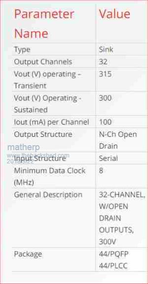 Here is my first cut at a Nixie clock circuit. Optionally uses DS3231 or GPS as the clock source. 2018-03-22_051900_Nixie_-_Project.pdf |
||||
| redrok Senior Member Joined: 15/09/2014 Location: United StatesPosts: 209 |
Hi matherp;While that chip has open drain outputs that "Sinks" current its not a current sink circuit that controls the value of the current being sunk. The classic "Current Sink" circuit controls the current. In my circuit diagram with 1.6K emitter resistors and the bases driven to 3.3V or 0V sinks about 2.7mA of current. I have changed the values to 2.2K to lower the sink current to about 1.3mA. I added the standard current sink circuit at the bottom of the Array circuit. The single transistor circuit is useful for individual things like Neon Lamps for the colons. The current will be: (3.3V - .6V) / 2.2K = 1.3mA or so.  Your circuit controls the current through the Nixie with the 15K anode resistor. Supply Voltage = 180V Running Voltage of the Nixie = 140V approximately (180V - 140V)/15K = 2.7mA BTW 2.7mA seems a bit high for the IN12A even though 2.7mA The IN12A is a relatively low lifetime Nixie. Same for the IN12B that I'm using. Lowering the current greatly increases the lifetime. The other Nixie I may be using is the small digit IN2. I will run this at 1mA. You may be interested in reading some of my "Notes On Nixies". redrok |
||||
| Martrogers Newbie Joined: 03/07/2016 Location: AustraliaPosts: 4 |
This is my effort to date using a MM but without multiplexing any tubes: https://www.youtube.com/watch?v=9vJLS7tbEQM https://www.youtube.com/watch?v=yJAfn53OvcU |
||||
| The Back Shed's forum code is written, and hosted, in Australia. | © JAQ Software 2026 |
