
|
|
Forum Index : Microcontroller and PC projects : Mounting these Shunts
| Author | Message | ||||
Chopperp Guru Joined: 03/01/2018 Location: AustraliaPosts: 1122 |
Hi Does anyone have any ideas on how to mount these types of current shunts? 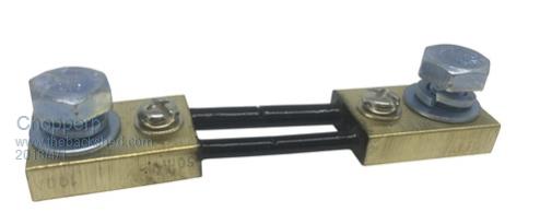 Thanks ChopperP ChopperP |
||||
| Alastair Senior Member Joined: 03/04/2017 Location: AustraliaPosts: 161 |
I mount them on a piece of perspex or pvc sheet so they are insulated and then mount that on whatever is the chassis. Cheers, Alastair |
||||
| Chopperp Guru Joined: 03/01/2018 Location: AustraliaPosts: 1122 |
Hi Alastair, Thanks fiir the reply. How do you actually attach them to the insulation material? The one I want to mount is slightly different in that the big bolt has the head on the underside with the nut on top. ChopperP ChopperP |
||||
| Zonker Guru Joined: 18/08/2012 Location: United StatesPosts: 772 |
Afternoon Gents... I work for a company, (Bitrode Corp.), that uses a lot of these types of metal based shunts.. Empro Shunts is the company that we get them from and maybe you can select one of theirs that come "pre-mounted"... Just a thought...  Edit: - You can also get them fully check out and they will come with a "CAL' certification sheet telling you the exact milli-ohm resistance of your sensor... PS - The one shown in the pix looks bent... probably bad because doing so creates micro fractures inside... So, probably a good idea to get a new one anyway... |
||||
| Chopperp Guru Joined: 03/01/2018 Location: AustraliaPosts: 1122 |
Hi Zonker The photo above came out of a Jaycar catalogue. Not a good advert. I needed a quick photo.They are not very robust. Mine is a bit different. Has thin fairly wide bars for the resistive element & they put small cuts in them to calibrate them. I see your point on micro fractures though. Not a mission critical application. Thanks ChopperpP ChopperP |
||||
| Alastair Senior Member Joined: 03/04/2017 Location: AustraliaPosts: 161 |
ChopperP I have used a few of that type but they are always a bit different. My first way was to remove the small screws and drill through the hole. I then used small bolts, with the heads below the pvc and up through the shunt holes. Nut & washer on top. A second nut was used to secure the sensing wire to the shunt. This worked fine but I found when I tightened the large nuts to secure the current carrying lugs, I could see the the base trying to turn about the small securing bolt and putting stress on the shunt conductors. Not really a problem if care is taken since this is not something you are unscrewing regularly. The next time I removed the big bolts and drilled through the pvc and fed the bolts up through the pvc and shunt. Again one washer and nut to secure the shunt another on top to secure the lug. The downside to this method is needing to have longer bolts of the right size. Where it was necessary to insulation behind the shunt I used a second piece of pvc behind the first to cover the bolt heads. If using the small ones you can countersink them enough. I hope the mud is clear enough to understand my explanation. Cheers, Alastair |
||||
| Chopperp Guru Joined: 03/01/2018 Location: AustraliaPosts: 1122 |
@ Zonker 60,000 amp shunts!!!! What are they used on or for? BTW did you ever get anywhere using a uMite for phase control? @Alistair I've just mounted one using your first method. Mine is a single bar (not two) but I will take on board what you said about the strain when tightening the big lugs. Yet to be done. I have previously mounted a 3 bar 100A, just using one long big bolt on one end on a high current terminal. Only a semi temporary/permanent set up. Understood perfectly what you meant (I think) Stupid design. I like some of Zonker's ones ChopperP ChopperP |
||||
| Boppa Guru Joined: 08/11/2016 Location: AustraliaPosts: 816 |
I've mounted dozens of these style shunts in trucks and boats doing it the same way Alistair does, using the big bolts as mounting bolts into a bit of perspex. I started off countersinking, but found that it was safer (esp if on the + leads) to put another bit of perspex behind, and fit 4 self tappers, one at each corner for mounting through both bits of perspex. Even then I made a habit of securing the leads on each end a bit away from the shunt with cableties or plasic u clamps just for extra support (being heavy unsupported cables in a high vibration/shock environment) I found I had bit a bit of variation between shunts, they really arent that accurate straight from the factory (esp the cheap ones!) but as long as they read high, I could easily trim them to accuracy by filing a bit off the shunt until it reads accurate against my reference meter- or you can calibrate them with series/parallel resistance to the meter itself |
||||
| The Back Shed's forum code is written, and hosted, in Australia. | © JAQ Software 2026 |
