
|
|
Forum Index : Microcontroller and PC projects : IEEE 485...
| Author | Message | ||||
| Zonker Guru Joined: 18/08/2012 Location: United StatesPosts: 772 |
Evening Gents I actually managed to get a few hours in on playing around with a possible MM application I would like to try... It involves trying to create a new status display device for one of the Bitrode battery testing machines at work. Currently, we use a 2 line character display for this device and I would like to fancy it up a bit by using a 470 based 5" color touch LCD and add some functions to it... Bitrode machines use a ColdFire based processor as their "Rack Controller" and uses one of the MPU's serial ports to transmit 9 bit based Rs-485 "packets" to the multiple test circuit "status displays"... The baud rate is 640K. The data packets should be going to Node Address "0" and "1", maybe more.. Getting more data on this...  Since i have one of G's excellent E-100 PCB's with a 5" LCD ready to go, I decided to use this as a "test bed" to help with the code testing. So, I started off by trying to write some "low level" code to try and get some data packets captured... I used a DS3695 transceiver IC and a resistor ladder to get the 5v signal down to something safe for the MM input. By shear luck, I managed to get a scope shot of one of the ColdFire transmitted packets being sent to the MM receiver... 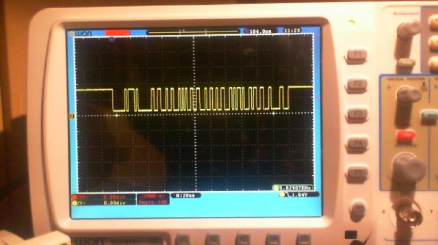 After several hours, I came up with this starting "test" program... ' 9-Bit Rs-485 Recieve test Option default none Option explicit Dim rxdat As string ' Rx data assembly buffer Dim a As string length 1 ' 9th bit - 1= adress - 0= data Dim b As string length 1 ' 8 bits of Rx data Dim address_match As float ' flag for data gate actions 'address_match=0 ' data gate is closed Dim node As string length 1 node=Chr$(0) ' node address = 0 Print "node ";Asc(node) 'Open "com1:640000,2048,got_rx,20,de,9bit" As #1 Open "com1:640000,2048,9bit" As #1 Do got_rx Loop Sub got_rx If Loc(#1)>2 Then a=Input$(1,#1) b=Input$(1,#1) If address_match Then ' if data gate open If a="0" Then ' if is data byte Print Asc(b); rxdat=rxdat+b ' add data byte to assembly buffer Else If Len(rxdat) Then Print " Buffer "; Print Len(rxdat) Print rxdat rxdat="" EndIf address_match=0 ' close data gate EndIf Else ' Node address ' If A="1" And b=node Then address_match=1 ' open data gate ' any address If A="1" Then address_match=1 ' open data gate Print "Node ";Asc(b) EndIf EndIf End Sub End After some "stare at it" time, you can see what I am trying to do here... I have a defined "Node" address set to "0". I decided not to use interrupts in the port OPEN statement. I just loop as fast as it goes, waiting for 2 or more bytes to be received. I use a "address match" flag to open the "data collection gate" and add received data bytes to the "rxdat" buffer string. As long as a "0" is being received as the 9th bit, I stuff it into the buffer. I also print the ASCII value of the data going into buffer as its being filled. If a "1" is received as the 9th bit, I close the data gate and print out the number to characters received and then print out the rxdata buffer... So, Originally, I was looking for a "1" on the 9th bit AND a match to the currently set "node address" setup at the start of the program. Well after getting NO data ever received, I changed the bottom of the routine to open up the data gate on ANY received node address. I then actually started to get some action from the running program, but it's seems to be making not much sense.. 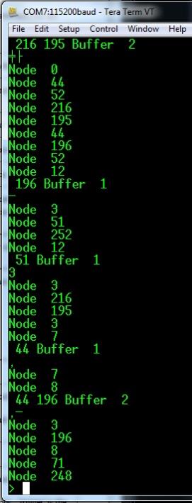 It seems like the data is getting "out of sync" somehow because I know there should be no data packets being sent to the "wild" number of "nodes" being detected... So, after looking over the manual again to see if I was doing something stupid, I noticed this warning MSG in the MM manual.. MMBasic does not check that data is printed or read to/from the COM port in pairs. If your program inadvertently sends or reads a single character it will disrupt all subsequent communications. Note also that in 9 bit mode the size of the transmit and receive buffers are effectively halved because each 9 bit data item is stored as two bytes. So, Maybe I am doing something wrong yet, or maybe this MM function is just to "unstable" to use properly... Not sure yet...  I wanted to ask if anyone out there has possibly used this 9 bit mode and had any luck with it..?? Maybe it would be better to get a C-Function for this instead. You could pass it a node address to listen for and a target data buffer to fill. When the packet is collected, a subroutine would be called to process the data... Anyway, Nuff babbling for now... Thanks in advance for any advice on this..!! |
||||
Azure Guru Joined: 09/11/2017 Location: AustraliaPosts: 446 |
That data stream looks like it is not a simple transmission, there seems to be some sort of encoding within it (think Manchester, NRZ, biphase, etc). The timing of the positive and negative transitions varies at different times but there does not seem to be a clear start and end to each word transmitted assuming there are a few words there. Not a problem but means you need to determine that encoding method. I would imagine that is why you can't make sense of the data (which is trying to read it as a simple serial stream). Are you able to look inside the LCD display unit to see what it is using to decode the data stream (what is between the rs485 line and it's processor). sometimes older type equipment designs used specific serial protocol chips to do the bit stream decoding. Failing that it would be good to check the timing on that signal train you captured to try and make progress from there. It would be good to measure the minimum pulse length on the smallest transitions and then use that to check if the next largest is 2x the smallest one. |
||||
| Azure Guru Joined: 09/11/2017 Location: AustraliaPosts: 446 |
Just to clarify something (in case I read and interpreted it incorrectly), the subject line for this post is IEEE485, which is a standard for sizing lead acid batteries and the chip you are using is a RS-485 differential line transmitter/receiver. You are trying to get the serial RS-485 working to build a MM with 5" LCD displaying data sent out on the RS-485 serial line? |
||||
| Geoffg Guru Joined: 06/06/2011 Location: AustraliaPosts: 3353 |
If I remember correctly the whole RS-485 functionality was put in some time ago at your request. I did a lot of testing at the time but I am prepared to bet that no one has used it since. Geoff Graham - http://geoffg.net |
||||
| Zonker Guru Joined: 18/08/2012 Location: United StatesPosts: 772 |
Hey Geoff.. Thanks for doing that.. I will continue to try and get more info on the data transmission stream and keep trying to get this working... The 8 bit Rs-485 works great.. This is the first time trying to get the 9 bit feature going and was hoping I was doing the code correctly to recover the data... the 470 MM allows the baud rate to reach high enough to try this... Thanks again for putting in the 9 bit into the code.!! I was hoping other people would have tried it...  |
||||
| matherp Guru Joined: 11/12/2012 Location: United KingdomPosts: 11166 |
RS-485 is an electrical specification and doesn't say anything about the use of the bits - just that there are 9 of them. I've just coded my interpretation of RS-485 capability into the Armmite but particularly as related to Modbus. For Modbus the 9th bit is a parity bit which can be properly set to even parity or else left as a zero. Are you sure you are looking at the correct bit in your example to indicate address? |
||||
bigmik Guru Joined: 20/06/2011 Location: AustraliaPosts: 2979 |
Hi Geoff, All, Hi Geoff, I used the 485 code (and EN pin) a few years ago (well, to be honest the code was mostly written by Peter Carnegie for me. I made minor changes) for an emulator for my work... (hey I am retiring in about 3 months). So your work was used and appreciated, As I required 2 com ports I would have loved 2 ports with EN pins.. Peter Carnegie achieved a good result for the second port but it did occasionally drop chrs but that wasn�t a major issue for me.. Anyway 485 8bit with EN worked a treat.. even on a 28pin �170 Regards, Mick Mick's uMite Stuff can be found >>> HERE (Kindly hosted by Dontronics) <<< |
||||
| Geoffg Guru Joined: 06/06/2011 Location: AustraliaPosts: 3353 |
Thanks for the feedback Mick. The best thing I ever did. It takes a year or two to get used to it but then you will wonder how you ever had the time for working. Geoff Geoff Graham - http://geoffg.net |
||||
| CaptainBoing Guru Joined: 07/09/2016 Location: United KingdomPosts: 2171 |
nice one Mik... well done... still got about 10 years to go  |
||||
| Zonker Guru Joined: 18/08/2012 Location: United StatesPosts: 772 |
I think the next thing to try is setting up another 470 MM and send 9 bit packets to the E-100 and get the receiver routines confirmed... I didn't get a chance to talk to the firmware guys today so I am not sure yet about what is being sent down the Rs-485 pipe... I do remember that each status display will show a timeout message if not kept alive by receiving data.. I looked at more scope shots and there is a lot of "short" data packets that seem to contain just the displays node address... This could be causing the crazy stuff.. I do remember testing this before for Geoff, but can't seem to locate the code I used then... Anyway, will post updates as things get going..!  Thanks again for the feedback..! EDIT: Update (a few days later)... Ok... So, I got rid of the coldfire setup, and connected the E-100 to an E-64 board sitting on a vector board with the E-64 acting as a transmitter and the E-100 the receiver.. The DS3695 IC is not being used either, just connecting the E-64 Tx pin (15) to the E-100 Rx pin (88) presented on the CON 8 IDC socket... I then striped down the test programs to the simplest form to test the data transfer taking place between them... ' 9-Bit Rs-485 Transmit test Option default none Option explicit Dim a As string length 1 ' 9th bit - 1= adress - 0= data Dim b As string length 1 ' 8 bits of Rx data Open "com1:640800,2048,9bit" As #1 tx_node1 tx_node2 End Sub tx_node1 Print #1,"1"+Chr$(0) ' node 0 Print #1,"0"+Chr$(65) ' A Print #1,"0"+Chr$(66) ' B Print #1,"0"+Chr$(67) ' C End Sub Sub tx_node2 Print #1,"1"+Chr$(1) ' node 1 Print #1,"0"+Chr$(68) ' D Print #1,"0"+Chr$(69) ' E Print #1,"0"+Chr$(70) ' F End Sub End This Tx code is a single pass thing that transmits 2 "Packets", 1 for node 0, one for node 1. I took a look on the scope and it shows 2 groups of 4 bytes being sent.. 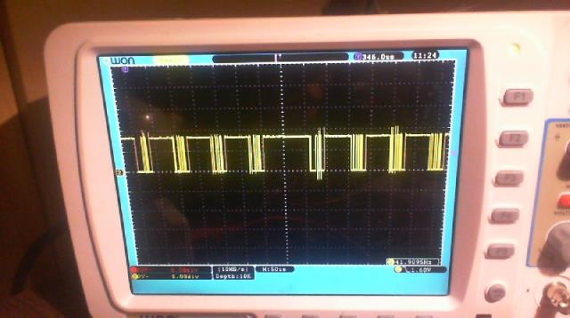 So, on the E-100 side, I had this program running, waiting to receive any data coming in.. ' 9-Bit Rs-485 Recieve test Option default none Option explicit Dim a As string length 1 ' 9th bit - 1= adress - 0= data Dim b As string length 1 ' 8 bits of Rx data Open "com1:640800,2048,9bit" As #1 Do got_rx Loop Sub got_rx If Loc(#1)>2 Then a=Input$(1,#1) b=Input$(1,#1) Print Asc(a);Asc(b) End Sub End I got this back on the output of the E-100.. 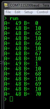 I got my data back and the correct node address target device codes, but I am not sure what the extra bytes that contain the "10" value are.. So, anyway, still working on this setup... PS - I did get a chance to get a copy of the "source" code for the coldfire and LCD display units... OMG, no wonder I couldn't figure it out..! I was thinking that they would send the data values and machine states as simple strings of data to the LCD displays and let the LCD display MCU code properly format the proper messages and data values on the LCD screen, (right)..?? Nope... As it turns out, they are sending direct commands and data directly to the 44780 LCD controller IC itself..!!  Yikes..! The code in the display board is just receiving the data stream, and is only knowing how to detect the LCD controller commands or data to properly control the "command / data" pin... Bummer... Yikes..! The code in the display board is just receiving the data stream, and is only knowing how to detect the LCD controller commands or data to properly control the "command / data" pin... Bummer...So, nuff babbling for now... So much for my "weekend project"... |
||||
| The Back Shed's forum code is written, and hosted, in Australia. | © JAQ Software 2026 |
