
|
|
Forum Index : Microcontroller and PC projects : A question about PIC 16F1708
| Author | Message | ||||
| larny Guru Joined: 31/10/2011 Location: AustraliaPosts: 349 |
I used MPLAB 8.92 to write & test a .asm programme for the 16F1708 PIC. I chose that PIC as it has Interrupt on Change on all inputs. I have found that IOC only works on PORTA inputs. When I change one of the PORTC inputs, the IOCCF flag does not change & the PIC won't exit Sleep - as it does for PORTA inputs. Is this due to a fault in the MPLAB software, or am I missing something? Any assistance will be appreciated. Len |
||||
Azure Guru Joined: 09/11/2017 Location: AustraliaPosts: 446 |
All 3 ports can be used for IOC. Master IOC needs to be enabled and every pin needs to have it's Interrupt on Positive and/or Negative edge enabled. The IOC flag for each pin are then used to determine which IOC pin caused the interrupt. This is covered fairly well in Chapter 13 of the manual for the chip. |
||||
| larny Guru Joined: 31/10/2011 Location: AustraliaPosts: 349 |
Thanks Azure. I had read chapter 13 & set IOCIE I also cleared ANSELA, B & C so the inputs are all digital. So it appears to be a software fault in MPLAB. I understand that MPLAB 8.92 does not fully support the 16F1708, so I assume that is the issue. I tried to use MPLABX but could not work out how to use it properly. So it looks as if I'll have to persevere with it & learn the ropes. Len |
||||
| Azure Guru Joined: 09/11/2017 Location: AustraliaPosts: 446 |
Have you set the IOC high or low enable flags for every pin on every port you want to create an IOC? |
||||
| larny Guru Joined: 31/10/2011 Location: AustraliaPosts: 349 |
I believe so, but I'll be very grateful if you or someone else can find an error or omission. Here is the relevant part of the code. Init banksel TRISA ;selects BANK 1 movlw 0x38 movwf TRISA ;RA5:3 i/p - RA3 is MCLR & not used clrf TRISB ;RB7:0 o/p movlw 0xF8 movwf TRISC ;RC7:3 i/p movlw 0x81 ;prescaler 1:4, internal clock movwf OPTION_REG ;disable RB pull up resistors banksel INLVLA ;selects Bank 7 movlw 0x30 movwf INLVLA ;RA5:4 set for Schmitt Trigger movlw 0x30 movwf IOCAP ;RA5:4 set for positive edge change clrf IOCAN ;RA5:4 negative edge change not used initially movlw 0xF8 movwf IOCCP ;RC7:3 set for positive edge change clrf IOCCN ;RC6:3 negative edge change not used initially banksel ANSELA ;selects BANK 3 clrf ANSELA clrf ANSELB clrf ANSELC banksel SLRCONA ;selects BANK 6 clrf SLRCONA clrf SLRCONB clrf SLRCONC banksel WPUA ;selects BANK 4 clrf WPUA clrf WPUB clrf WPUC banksel PORTA ;selects BANK 0 movlw 0x00 ;tempLC to be 0x07 movwf PORTA movwf PORTC ;turn MOSFETs off bsf INTCON, IOCIE ;bit 3 : awake on IOC bsf INTCON, TMR0IE ;bit 5 : enable TMR0 overflow return |
||||
| Azure Guru Joined: 09/11/2017 Location: AustraliaPosts: 446 |
For setup: Set TRISA/B/C for each IOC port pin to input Set INLVLA/B/C threshold level for each IOC pin Set IOCAP, IOCBP, IOCCP for each IOC positive edge Set IOCAN, IOCBN, IOCCN for each IOC negative edge After initial setup: You need to enable INTCON bit 3 (interrupt on change enable) and bit 7 (global interrupt enable). While program is running: On an interrupt you can first check INTCON bit 0 to see if an interrupt on change has occurred on at least one interrupt on change pin. Then Check each IOCAF, IOCBF, IOCCF to see which pin interrupted. To clear interrupt that occurred: Write to IOCAF, IOCBF, IOCCF after processing interrupt to clear flag. In looking at your init routine there is no setting INTLVC or INTCON GIE (bit 7), I did not check if you preceeded any of these with the correct banksel. |
||||
| larny Guru Joined: 31/10/2011 Location: AustraliaPosts: 349 |
Thanks Azure. See my comments in red below. |
||||
| Azure Guru Joined: 09/11/2017 Location: AustraliaPosts: 446 |
OK, you should have mentioned in your first post that you are trying to wake from sleep and are not using interrupts. You listed code does not set INTLVC so port C will default to ST mode. You should also make sure to clear IOCAF and IOCCF before going to sleep. If that does not work make sure you can read the IOCCF flag bits changing for each appropriate port C pin during normal operation (not in SLEEP). |
||||
| larny Guru Joined: 31/10/2011 Location: AustraliaPosts: 349 |
Thanks Azure I'll programme it into a PIC & see if it works. If so, that will prove my presumption that the MBLAB software is faulty. 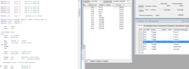 |
||||
| Azure Guru Joined: 09/11/2017 Location: AustraliaPosts: 446 |
Sorry I cannot read the text in the images they are too blurry. You need to make sure the interrupt flags are cleared before you go to sleep, otherwise they will not sense a change and trigger the wake up. I think you misunderstood my last point. As part of troubleshooting the problem you need to: Make sure the connections to port C can be read and match the input on them; Test them in both off and on states. To do this you need to write some test code to make sure you can read port C pins while it is not asleep and see that input low and high signals are being read correctly. This is for testing your connections and setup of port C it would not be part of your normal code. |
||||
| larny Guru Joined: 31/10/2011 Location: AustraliaPosts: 349 |
Thanks Azure. I think I did understand your last point but you may a missed my point. The point I was trying to make is that the IOCCF is always 0 regardless of whether PORTC is changed in sleep or out of sleep. Whereas, the IOCAF changes as expected. That's why I think it is a MPLAB software fault. I read somewhere that MPLAB 8.92 does not fully support this PIC. See the attachments. 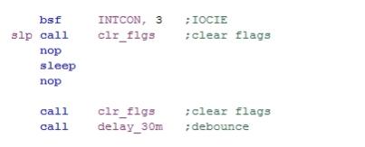 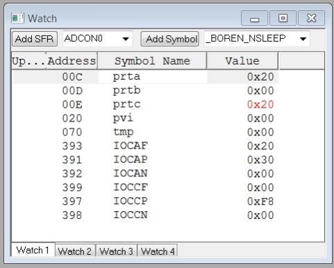 |
||||
| larny Guru Joined: 31/10/2011 Location: AustraliaPosts: 349 |
Azure I did as you suggested in your last point. I inserted some nop statements. I changed PORTA at the first nop & PORTC at the second. The attachment shows the result. IOCAF changed, but not IOCCF. I made them larger, so I hope you can read it this time. 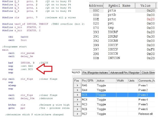 |
||||
| Azure Guru Joined: 09/11/2017 Location: AustraliaPosts: 446 |
Are you doing this only as a software simulation or working with a real chip? For the purpose of testing port C function you should not change any pin on Port A and just change a pin on port C to test it. How are you clearing the flags? |
||||
| larny Guru Joined: 31/10/2011 Location: AustraliaPosts: 349 |
I'm simulating with MPLAB. I did that - no difference. IOCCF Is still 0x00. Here is the sub routine that clears the flags. clr_flgs ;Clear flag(s) IOCAF & IOCCF banksel IOCAF ;selects Bank 7 movlw 0xFF xorwf IOCAF, w andwf IOCAF, f ;this resets IOCAF - see spec p. 147 movlw 0xFF xorwf IOCCF, w andwf IOCCF, f ;this resets IOCCF - see spec p. 147 banksel PORTA ;selects Bank 0 return |
||||
| matherp Guru Joined: 11/12/2012 Location: United KingdomPosts: 11166 |
IMHO you are expecting far too much of simulation. You have to test on the silicon to see if there is an issue. |
||||
| larny Guru Joined: 31/10/2011 Location: AustraliaPosts: 349 |
Thanks for the comment matherp. I have written many PIC programmes & tested them successfully in MPLAB before programming a PIC. So I don't see why it won't work in this case. However, my next step is to programme a PIC & test. By the way, what does IMHO mean? Len |
||||
| Azure Guru Joined: 09/11/2017 Location: AustraliaPosts: 446 |
In My Humble Opinion |
||||
| The Back Shed's forum code is written, and hosted, in Australia. | © JAQ Software 2026 |
