
|
|
Forum Index : Microcontroller and PC projects : Open-circuit via!
| Author | Message | ||||
Grogster Admin Group Joined: 31/12/2012 Location: New ZealandPosts: 9933 |
This is new. I have never seen this before on any PCB, which is a good thing! Latest board I am playing with, I could not work out why the HC12 module refused to talk back to the MM chip on COM1. No amount of tinkering fixed it. I even removed the HC12 thinking perhaps I had a dud - not that I have ever had any factory duds on those yet either. I thought I probably should do a quick continuity test with my multi-meter(set on junction test, which only allows about 0.5mA of current to flow). OK, circuit through SET line to MM chip. Circuit through TXD to MM chip. ......NO circuit from RXD to MM chip. Well, well, well. Checked a few times, and pulled out the MM chip to be sure. No circuit. Checked one of the other boards, and there WAS a circuit on those ones. I would have to pick up the dud one to assemble. Go figure. Can't say I have ever seen this before(thank God!), and surprised that it got past the flying probe test in the factory. I fixed it by drilling out the via, and using some thin enamelled copper wire as a link from the HC12 on the top of the PCB, to the appropriate pad on the MM chip on the bottom. Still, a good curvy ball thing, that one! Everything is working as expected now, and the HC12 responds correctly. Smoke makes things work. When the smoke gets out, it stops! |
||||
| Bill7300 Senior Member Joined: 05/08/2014 Location: AustraliaPosts: 159 |
I struck that problem once, way back in the 1980s, in a Maestro (from memory) dial-up modem. I think my last few strands of hair jumped ship in the frustration of trying to fault find that particular issue. That board was actually Australian made too. At the time, the design was considered the ant's pants in terms or latest chip usage, speed etc so its failure to come to life had me worried that I might have bought the proverbial pig in the poke, having jumped in too early in the product cycle. I luckily stopped short of lifting any chips, although the suspect via might have been under one. Once fixed with a flying trace of wire-wrap wire though, that extremely useful commodity,the modem saw continuous service through to the end of the dial up era. Bill |
||||
| Grogster Admin Group Joined: 31/12/2012 Location: New ZealandPosts: 9933 |
Indeed. What with the reliability of modern PCB manufacture processes, I had to convince myself it was indeed an o/c via, so I tested it about five times to be totally sure!  Not something I have ever seen before. Vias are usually 100% reliable. My fix:  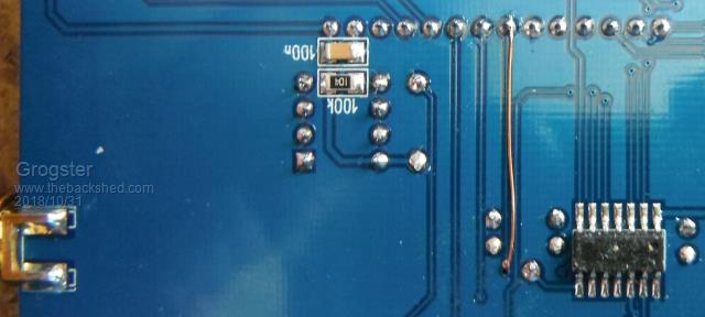 Smoke makes things work. When the smoke gets out, it stops! |
||||
Azure Guru Joined: 09/11/2017 Location: AustraliaPosts: 446 |
Have seen some back around the time of my early arcade video game pcb repair days. Totally agree they are very hard to track down because it is not something you normally suspect to be faulty. We would just scrape back the resist on both sides and solder a piece of wire wrap wire through the hole as if it were a home made double sided PCB. |
||||
bigmik Guru Joined: 20/06/2011 Location: AustraliaPosts: 2979 |
Hi Grogs, All, I have had the occasional short between traces (usually some fine hair when the PCB was etched that acted as a `Resist') and not long ago I had a report of 2 broken traces on a MuP PCB.. These are rare but is always a possibility. On a different note, I invested about $5k back in circa 1981 on a PCB for a Z80 box with a friend of mine.. we came up with a `PCB copy protection' of using a via between an address line and a data line and before we assembled the boards I drilled it out with a VERY fine drill. I know of at least 2 people/groups who tried to make photographic copies of my board and failed due to this protection.. (it would have been an extremely hard thing to find) At the time I patted myself on the back for we made about $200 between the two of us in profit and put in many hours of build time so I reckon I got about $1per hr for my work.. Anyway, I share your frustrations.. Kind Regards, Mick Mick's uMite Stuff can be found >>> HERE (Kindly hosted by Dontronics) <<< |
||||
| CaptainBoing Guru Joined: 07/09/2016 Location: United KingdomPosts: 2171 |
When I get PCBs made, there is a stage called "electrical test" - I had always figured this would catch shorts and o/c. This is an assumption on my part so out of ignorance, what is "electrical test"? |
||||
| Frank N. Furter Guru Joined: 28/05/2012 Location: GermanyPosts: 1071 |
Two days ago I read about this problem on www.microcontroller.net - Quality problems despite "electrical test"! There they came to the opinion that (in order to save costs) no overproduction at printed circuit boards is manufactured. If then which ones are not ok they will be "well tested". Frank |
||||
| Grogster Admin Group Joined: 31/12/2012 Location: New ZealandPosts: 9933 |
@ Captain - I always assumed the electrical test was the flying probe test, which is designed to catch those exact manufacturing faults. Perhaps I too am wrong about that. Smoke makes things work. When the smoke gets out, it stops! |
||||
| bigmik Guru Joined: 20/06/2011 Location: AustraliaPosts: 2979 |
Hi All, FYI The correct link is www.mikrocontroller.net/ I remember reading/seeing somewhere that 100% electrical testing of PCBs doesn't mean what you and I would think that it should mean.. I will see if I can find that reference again. Kind Regards, Mick Mick's uMite Stuff can be found >>> HERE (Kindly hosted by Dontronics) <<< |
||||
| The Back Shed's forum code is written, and hosted, in Australia. | © JAQ Software 2026 |
